Dodge Caliber. Manual - part 1407


  Index      Dodge     Dodge Caliber - service repair manual 2007 year


Search            


Content   ..  1405  1406  1407  1408   ..


Dodge Caliber. Manual - part 1407


4.

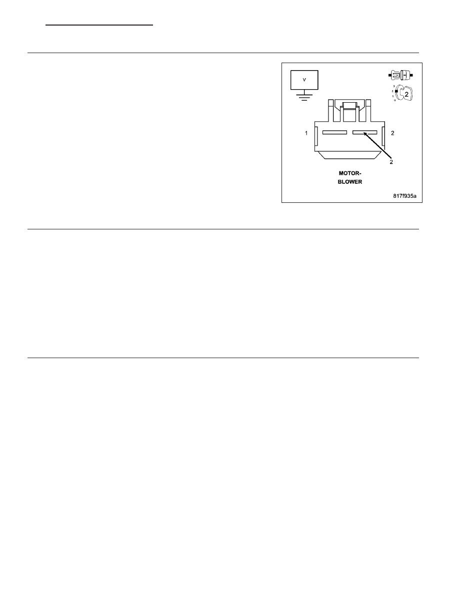
CHECK FOR 12 VOLTS TO THE BLOWER MOTOR

Turn the ignition off.

Disconnect the Blower Motor harness connector.

Turn the ignition on.

Turn the Blower Motor control on.

Using a volt meter measure the voltage on the (C7) Blower Motor Con-
trol circuit in the Blower Motor harness connector.

Does the volt meter read 12 volts?

Yes

>> Go To 5

No

>> Go To 6

5.

CHECK FOR A BLOCKAGE STALLING THE BLOWER MOTOR

Turn the ignition off.

Remove the Blower Motor from the HVAC housing assembly.

Look for anything on the Blower Motor and in the HVAC housing that is physically preventing Blower Motor oper-
ation.

Is anything physically preventing Blower Motor operation?

Yes

>> Repair as necessary. Also, check Blower Motor for proper operation. Reinstall, or replace the Blower

Motor as necessary in accordance with the service information.

No

>> Replace the Blower Motor in accordance with the service information.

Perform BODY VERIFICATION TEST – VER 1. (Refer to 8 - ELECTRICAL/ELECTRONIC CONTROL
MODULES - STANDARD PROCEDURE).

6.

CHECK FOR CHAFING IN THE (C7) BLOWER MOTOR CONTROL CIRCUIT

Turn the ignition off.

Check the (C7) Blower Motor Control circuit for wire chaffing.

Is any wire chaffing present?

Yes

>> Repair the wire chafing on the (C7) Blower Motor Control circuit.

Perform BODY VERIFICATION TEST - VER 1. (Refer to 8 - ELECTRICAL/ELECTRONIC CONTROL
MODULES - STANDARD PROCEDURE).

No

>> Replace the Totally Integrated Power Module (TIPM) in accordance with the service information.

Perform BODY VERIFICATION TEST - VER 1. (Refer to 8 - ELECTRICAL/ELECTRONIC CONTROL
MODULES - STANDARD PROCEDURE).

PM

HEATING & AIR CONDITIONING ELECTRICAL DIAGNOSTICS

24 - 45

B10BF–CONDENSER FAN CONTROL CIRCUIT HIGH (TIPM)

For a complete wiring diagram Refer to Section 8W.

When Monitored:
With the ignition on. Battery voltage greater than 10.4 volts.

Set Condition:
If the Totally Integrated Power Module (TIPM) detects a shorted high condition in the (N112) High Speed Radi-
ator Fan Control circuit.

Possible Causes

(N112) HIGH SPEED RADIATOR FAN CONTROL CIRCUIT SHORTED TO BATTERY VOLTAGE

RADIATOR FAN MOTOR

TOTALLY INTEGRATED POWER MODULE (TIPM)

Diagnostic Test

1.

VERIFY DTC IS ACTIVE

Turn the ignition on.

With the scan tool, erase DTCs.

Turn the ignition off, wait 10 seconds, and turn the ignition on.

With the scan tool, actuate the Radiator Fan.

With the scan tool, read DTCs.

Does the scan tool display active: B10BF-CONDENSER FAN CONTROL CIRCUIT HIGH?

Yes

>> With the scan tool, de-actuate the Radiator Fan. Then, Go To 2

No

>> With the scan tool, de-actuate the Radiator Fan. The condition that caused this symptom is currently not

present. Check for an intermittent condition by inspecting the related wiring harness for chafed, pierced,
pinched, and partially broken wires. Also, inspect the related connectors for broken, bent, pushed out,
spread, corroded, or contaminated terminals. Repair as necessary.

Perform BODY VERIFICATION TEST – VER 1. (Refer to 8 - ELECTRICAL/ELECTRONIC CONTROL
MODULES - STANDARD PROCEDURE).

2.

CHECK (N112) HIGH SPEED RADIATOR FAN CONTROL CIRCUIT FOR A SHORT TO BATTERY VOLTAGE

Turn the ignition off

Disconnect the TIPM C11 harness connector.

Disconnect the Radiator Fan Motor harness connector.

Turn the ignition on.

Using a volt meter, measure the voltage on the (N112) High Speed Radiator Fan Control circuit at the Radiator Fan
Motor harness connector.

Does the volt meter read 10 volts, or above?

Yes

>> Repair the (N112) High Speed Radiator Fan Control circuit for a short to battery voltage.

Perform BODY VERIFICATION TEST – VER 1. (Refer to 8 - ELECTRICAL/ELECTRONIC CONTROL
MODULES - STANDARD PROCEDURE).

No

>> Go To 3

24 - 46

HEATING & AIR CONDITIONING ELECTRICAL DIAGNOSTICS

PM

3.

CHECK (Z823) GROUND CIRCUIT FOR AN OPEN

Turn the ignition off.

Reconnect the TIPM C8 harness connector.

NOTE: The test light should illuminate brightly. Compare the brightness to that of a direct connection to the
battery.
Using a 12-volt test light connected to 12 volts, probe the (Z823) Ground circuit at the Condenser Fan Motor har-
ness connector.

Does the test light illuminate brightly?

Yes

>> Go To 4

No

>> Repair the excessive resistance in the (Z823) Ground circuit.

Perform BODY VERIFICATION TEST – VER 1. (Refer to 8 - ELECTRICAL/ELECTRONIC CONTROL
MODULES - STANDARD PROCEDURE).

4.

CHECK RADIATOR FAN MOTOR

Ignition on, engine not running.

With the scan tool, actuate the Radiator Fan.

Using a 12-volt test light connected to ground, probe the (C123) Condenser Fan Control Output circuit at the Con-
denser Fan Motor harness connector.

Does the test light illuminate brightly and flash on and off?

Yes

>> With the scan tool, de-actuate the Condenser Fan. Then, replace the Condenser Fan Motor in accor-

dance with the Service Information.

Perform BODY VERIFICATION TEST – VER 1. (Refer to 8 - ELECTRICAL/ELECTRONIC CONTROL
MODULES - STANDARD PROCEDURE).

No

>> With the scan tool, de-actuate the Condenser Fan. Then, Go To 5

5.

INSPECT RELATED WIRING

NOTE: Before continuing, check the TIPM harness connector terminals for corrosion, damage, or terminal
push out. Repair as necessary.
Using the schematics as a guide, inspect the related wiring harness and connectors.

Pay particular attention to all Power and Ground circuits.

Were any problems found?

Yes

>> Repair as necessary.

Perform BODY VERIFICATION TEST – VER 1. (Refer to 8 - ELECTRICAL/ELECTRONIC CONTROL
MODULES - STANDARD PROCEDURE).

No

>> Replace the TIPM in accordance with the Service Information.

Perform the BODY VERIFICATION TEST – VER 1. (Refer to 9 - ENGINE - STANDARD PROCEDURE)

PM

HEATING & AIR CONDITIONING ELECTRICAL DIAGNOSTICS

24 - 47

B10BE–CONDENSER FAN CONTROL CIRCUIT LOW (TIPM)

For a complete wiring diagram Refer to Section 8W.

When Monitored:
With the ignition on. Battery voltage greater than 10.4 volts.

Set Condition:
If the Totally Integrated Power Module (TIPM) detects a shorted low condition in the (C123) Condenser Fan
Control circuit.

Possible Causes

(C123) CONDENSER FAN CONTROL OUTPUT CIRCUIT SHORTED TO GROUND

CONDENSER FAN MOTOR

TIPM

Diagnostic Test

1.

VERIFY DTC IS ACTIVE

Turn the ignition on.

With the scan tool, erase TIPM DTCs.

Turn the ignition off, wait 10 seconds, and turn the ignition on.

With the scan tool, actuate the Condenser Fan.

With the scan tool, read TIPM DTCs.

Does this DTC reset?

Yes

>> With the scan tool, de-actuate the Condenser Fan. Then, Go To 2

No

>> With the scan tool, de-actuate the Condenser Fan. Then, check for an intermittent condition by inspect-

ing the related wiring harness for chafed, pierced, pinched, and partially broken wires. Also, inspect the
related connectors for broken, bent, corroded, and contaminated terminals.

Perform BODY VERIFICATION TEST – VER 1. (Refer to 8 - ELECTRICAL/ELECTRONIC CONTROL
MODULES - STANDARD PROCEDURE).

2.

CHECK (C123) CONDENSER FAN CONTROL OUTPUT CIRCUIT FOR A SHORT TO GROUND

Turn the ignition off.

Disconnect the TIPM C8 harness connector.

Disconnect the Condenser Fan Motor harness connector.

Measure the resistance of the (C123) Condenser Fan Control Output circuit between ground and the Condenser
Fan Motor harness connector.

Is the resistance below 100 ohms?

Yes

>> Repair the (C123) Condenser Fan Control Output circuit for a short to ground.

Perform BODY VERIFICATION TEST – VER 1. (Refer to 8 - ELECTRICAL/ELECTRONIC CONTROL
MODULES - STANDARD PROCEDURE).

No

>> Go To 3

24 - 48

HEATING & AIR CONDITIONING ELECTRICAL DIAGNOSTICS

PM


Content   ..  1405  1406  1407  1408   ..