Dodge Caliber. Manual - part 137


  Index      Dodge     Dodge Caliber - service repair manual 2007 year


Search            


Content   ..  135  136  137  138   ..


Dodge Caliber. Manual - part 137


3.

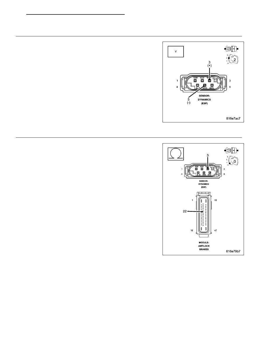
CHECK (G4) DYNAMICS SENSOR SUPPLY CIRCUIT & (G94) DYNAMICS SENSOR GROUND CIRCUIT
FUNCTION

Disconnect the Dynamics Sensor harness connector.

Turn the ignition on.

Measure the voltage between the (G4) Dynamics Sensor Supply Circuit
and the (G94) Dynamics Sensor Ground Circuit.

Is the voltage above 4.5 volts?

Yes

>> Replace the Dynamics Sensor in accordance with the Ser-

vice Information.

Perform ABS VERIFICATION TEST. (Refer to 5 - BRAKES -
STANDARD PROCEDURE).

No

>> Go To 4

4.

CHECK (G4) DYNAMICS SENSOR SUPPLY CIRCUIT FOR HIGH RESISTANCE

Turn the ignition off.

Disconnect the Anti-Lock Brakes Module harness connector.

Measure the resistance of the (G4) Dynamics Sensor Supply circuit
between the Dynamics Sensor harness connector and the Anti-Lock
Brakes Module harness connector.

Is the resistance below 5.0 ohms?

Yes

>> Go To 5

No

>> Repair the (G4) Dynamics Sensor Supply circuit for high

resistance.

Perform ABS VERIFICATION TEST. (Refer to 5 - BRAKES -
STANDARD PROCEDURE).

PM

BRAKES - ABS ELECTRICAL DIAGNOSTICS

5 - 249

5.

CHECK (G94) DYNAMICS SENSOR GROUND CIRCUIT FOR HIGH RESISTANCE

Measure the resistance of the (G94) Dynamics Sensor Ground circuit
between the Dynamics Sensor harness connector and the Anti-Lock
Brakes Module harness connector.

Is the resistance below 5.0 ohms?

Yes

>> Replace the Anti-Lock Brakes Module in accordance with

the Service Information.

Perform ABS VERIFICATION TEST. (Refer to 5 - BRAKES -
STANDARD PROCEDURE).

No

>> Repair the (G94) Dynamics Sensor Ground circuit for high

resistance.

Perform ABS VERIFICATION TEST. (Refer to 5 - BRAKES -
STANDARD PROCEDURE).

5 - 250

BRAKES - ABS ELECTRICAL DIAGNOSTICS

PM

C2115–DYNAMICS SENSOR SUPPLY VOLTAGE HIGH

For a complete wiring diagram Refer to Section 8W.

PM

BRAKES - ABS ELECTRICAL DIAGNOSTICS

5 - 251

When Monitored:
Upon ignition on, prior to switching the (G4) Dynamics Sensor Supply circuit power on.

Set Condition:
If the Anti-Lock Brakes Module detects voltage on the (G4) Dynamics Sensor Supply circuit when the circuit’s
power is turned off.

Possible Causes

WIRING HARNESS, TERMINAL, CONNECTOR DAMAGE

(G4) DYNAMICS SENSOR SUPPLY CIRCUIT SHORTED TO VOLTAGE

ANTI-LOCK BRAKES MODULE

1.

VERIFY DTC IS ACTIVE

Turn the ignition on.

With the scan tool, read and record ABS DTCs.

With the scan tool, read and record Environmental Data (EV Data).

With the scan tool, erase ABS DTCs.

Cycle the ignition switch.

With the scan tool, read ABS DTCs.

Does this DTC reset?

Yes

>> Go To 2

No

>> Perform the ABS Intermittent Condition diagnostic procedure in this Section.

Refer to the ABS-INTERMITTENT CONDITION TEST. (Refer to 5 - BRAKES - DIAGNOSIS AND TEST-
ING)

2.

INSPECT RELATED WIRING HARNESS, TERMINALS, & CONNECTORS

Turn the ignition off.

Check all related wiring for pinched, chafed, pierced, and partially broken wires.

Check all related connectors for broken, bent, pushed out, and corroded terminals.

Were any problems found?

Yes

>> Repair as necessary.

Perform ABS VERIFICATION TEST. (Refer to 5 - BRAKES - STANDARD PROCEDURE).

No

>> Go To 3

3.

CHECK (G4) DYNAMICS SENSOR SUPPLY CIRCUIT SHORT FOR A SHORT TO VOLTAGE

Disconnect the Anti-Lock Brakes Module harness connector.

Turn the ignition on.

Measure the voltage of the (G4) Dynamics Sensor Supply Circuit.

Is the voltage above 0.2 volts?

Yes

>> Repair the (G4) Dynamics Sensor Supply Circuit for a short

to voltage.

Perform ABS VERIFICATION TEST. (Refer to 5 - BRAKES -
STANDARD PROCEDURE).

No

>> Replace the Anti-Lock Brakes Module in accordance with

the Service Information.

Perform ABS VERIFICATION TEST. (Refer to 5 - BRAKES -
STANDARD PROCEDURE).

5 - 252

BRAKES - ABS ELECTRICAL DIAGNOSTICS

PM


Content   ..  135  136  137  138   ..