Dodge Caliber. Manual - part 1309


  Index      Dodge     Dodge Caliber - service repair manual 2007 year


Search            


Content   ..  1307  1308  1309  1310   ..


Dodge Caliber. Manual - part 1309


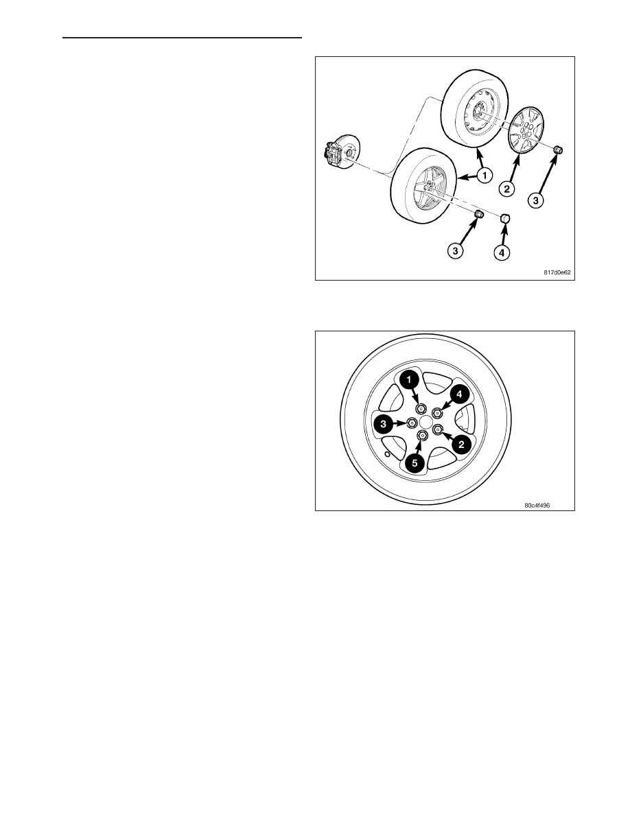
1. Clean wheel mounting surfaces, removing any

build-up of corrosion. It is important to have good
metal-to-metal contact between the wheel and
vehicle.

2. Position the tire and wheel assembly (1) on the

wheel mounting studs using the hub pilot as a
guide. Place and hold the wheel flush up against
the mounting surface.

NOTE: Always use the original (OEM) style wheel
mounting (lug) nuts. Do not use replacement parts
of lesser quality or substitute design.

3. Install and lightly snug all five wheel mounting (lug)

nuts (3) Do not tighten at this time.

4. If applicable, install the wheel center cap.

5. Lower the vehicle.

6. Progressively tighten all wheel mounting nuts in the

proper sequence shown. Tighten nuts to a final
torque of 135 N·m (100 ft. lbs.).

TIRE AND WHEEL ASSEMBLY - STEEL WHEEL

WARNING: Installing wheels without good metal-to-metal contact with the mounting surface could cause
loosening of the wheel mounting (lug) nuts. This could adversely affect the safety and handling of the vehi-
cle.

NOTE: Never use oil or grease on studs or wheel mounting (lug) nuts.

PM

TIRES/WHEELS - SERVICE INFORMATION

22 - 63

1. Clean the wheel mounting surfaces, removing any

build-up of corrosion. It is important to have good
metal-to-metal contact between the wheel and
vehicle.

2. Position the tire and wheel assembly (1) on the

wheel mounting studs using the hub pilot as a
guide. Place and hold the wheel flush up against
the mounting surface.

3. Align the valve notch in the wheel cover with the

valve stem on the wheel and install the wheel
cover over the studs.

NOTE: Always use the original (OEM) style wheel
mounting (lug) nuts. Do not use replacement parts
of lesser quality or substitute design.

4. Install and lightly snug all five wheel mounting (lug)

nuts (3) Do not tighten at this time.

5. Lower the vehicle.

6. Progressively tighten all wheel mounting (lug) nuts

in the proper sequence shown. Tighten the nuts to
a final torque of 135 N·m (100 ft. lbs.).

22 - 64

TIRES/WHEELS - SERVICE INFORMATION

PM

SPECIAL TOOLS

TIRES AND WHEELS

Dial Indicator C-3339A

Press, Ball Joint C-4150A

PM

TIRES/WHEELS - SERVICE INFORMATION

22 - 65

TIRE PRESSURE MONITORING - SERVICE INFORMATION

DESCRIPTION

The Tire Pressure Monitoring (TPM) system monitors air pressure in the four road tires (excludes spare). Pressure
in the spare tire is not monitored. A premium system specifying how many tires are low and where they are located
is used on this vehicle.

TPM alerts the driver when tire pressure falls below predetermined thresholds. (Refer to 22 - TIRES/WHEELS/TIRE
PRESSURE MONITORING - OPERATION)

The TPM systems are controlled by the Wireless Control Module (WCM), commonly referred to as the Sentry Key
Remote Entry Module (SKREEM).

There is a sensor (transmitter) in each of the vehicle’s four road wheels that operates on a 315 MHz radio fre-
quency. Export vehicle sensors operate on a 433 MHz radio frequency.

Premium TPM transponders are located in three of the four wheel wells of the vehicle are used to provide the WCM
with the location of the tire pressure sensors on the vehicle. The transponders are located in the left front, left rear
and right rear wheel wells.

An indicator lamp located in the instrument cluster and messages in the Electronic Vehicle Information Center
(EVIC) are used to communicate system information.

For further information, refer to the Owners Manual or the appropriate diagnostic information.

OPERATION

The Tire Pressure Monitoring (TPM) system uses radio and sensor technology to monitor tire air pressure levels.
Sensors, mounted to each road wheel as part of the valve stem, transmit an RF signal indicating their individual
pressure to a receiver located in the Wireless Control Module (WCM), commonly referred to as the Sentry Key
Remote Entry Module (SKREEM). These transmissions occur approximately once every minute at speeds over 15
mph (24 km/h). The Tire Pressure Monitoring system remains active even if no tire pressure related message is
displayed.

The sensors lay dormant (Park Mode), then wake and start transmitting (Drive Mode) when the vehicle first reaches
speeds over 15 mph (24 km/h). Once the wheels stop rotating for a period of approximately 20 minutes, the sensors
shut down until again awaken. Although not transmitting as when in Drive Mode, while in Park Mode, the sensors
still transmit approximately once every 13 hours to let the receiver know air pressure status at that time. Sensors
will also transmit when a pressure change of one psi (seven kPa) or more is detected during that period. For more
information on sensors, (Refer to 22 - TIRES/WHEELS/TIRE PRESSURE MONITORING/SENSOR - OPERATION).

Premium TPM transponders located in three of the four wheel wells of the vehicle are used to provide the WCM
with the location of the tire pressure sensors on the vehicle. The transponders are located in the left front, left rear
and right rear wheel wells. A fourth transponder is not necessary in the remaining wheel well due to the process-
of-elimination theory. Once the system knows the location of the first three sensors it assumes the location of the
fourth tire pressure sensor is in the right front tire. For more information, (Refer to 22 - TIRES/WHEELS/TIRE
PRESSURE MONITORING/TRANSPONDER - OPERATION).

If the system detects that the tire pressure in any road tire is going low, beyond the Low Pressure (lamp) ON thresh-
old (see following table), the TPM system will continuously illuminate an indicator lamp. Also, a message will be
displayed in the instrument cluster. The text message will indicate which tire is low and the display will show all
current tire pressures, the low tire will be flashing with its pressure value. This message will be displayed for the rest
of the ignition cycle, or until the Low Tire pressure condition has been corrected. A chime will sound upon initial
detection. Once pressure in the suspect tire raises above the Low Pressure (lamp) OFF Threshold, the lamp will go
out and the system returns to normal within approximately two minutes time. If a message center button is pressed,
the message is replaced by the new message requested; however, if the Low Tire condition has not been corrected,
the Low Tire pressure message will again be displayed.

If a system fault is detected, the indicator lamp will flash on/off for 60 seconds, once every 10 minutes.

For further information, refer to the Owners Manual or the Appropriate Diagnostic Information.NOTE:
To determine the pressure thresholds for a vehicle, refer to the Tire Inflation Pressure (Placard) Label found on the
Driver’s B-Pillar, then apply the placard pressure to the following table.

22 - 66

TIRES/WHEELS - SERVICE INFORMATION

PM


Content   ..  1307  1308  1309  1310   ..