Content .. 1303 1304 1305 1306 ..
Dodge Caliber. Manual - part 1305
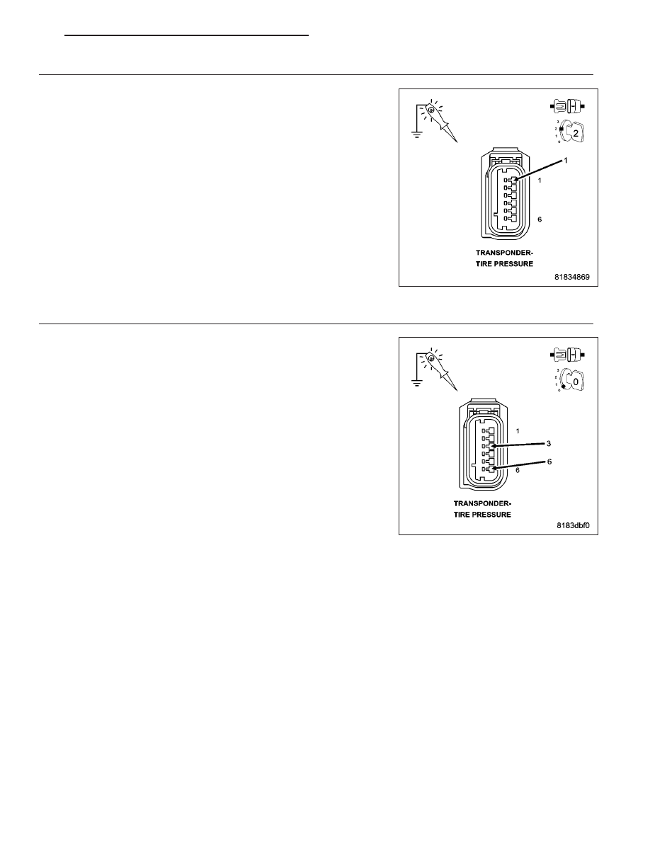
2.
(F202) FUSED IGNITION SWITCH OUTPUT (RUN) CIRCUIT OPEN OR HIGH RESISTANCE
Turn the ignition on.
Using a 12–volt test light connect to ground, check the (F202) Fused
Ignition Switch Output (Run) circuit.
NOTE: The test light should be illuminated and bright. Compare
the brightness to that of a direct connection to the battery.
Is the test light illuminated and bright?
Yes
>> Go to 3
No
>> Repair the (F202) Fused Ignition Switch Output (Run) circuit
for an open circuit or high resistance.
Perform TPM VERIFICATION TEST. (Refer to 22 - TIRES/
WHEELS/TIRE PRESSURE MONITORING - STANDARD
PROCEDURE)
3.
(Z965) GROUND CIRCUIT(S) OPEN OR HIGH RESISTANCE
Using a 12–volt test light connect to 12 volts, check each of the (Z965)
Ground circuit(s).
NOTE: The test light should be illuminated and bright. Compare
the brightness to that of a direct connection to the battery.
Is the test light illuminated and bright?
Yes
>> Go to 4
No
>> Repair the (Z965) Ground circuit(s) for an open circuit or
high resistance.
Perform TPM VERIFICATION TEST. (Refer to 22 - TIRES/
WHEELS/TIRE PRESSURE MONITORING - STANDARD
PROCEDURE)
PM
TIRES/WHEELS - ELECTRICAL DIAGNOSIS
22 - 47