Content .. 1237 1238 1239 1240 ..
Dodge Caliber. Manual - part 1239
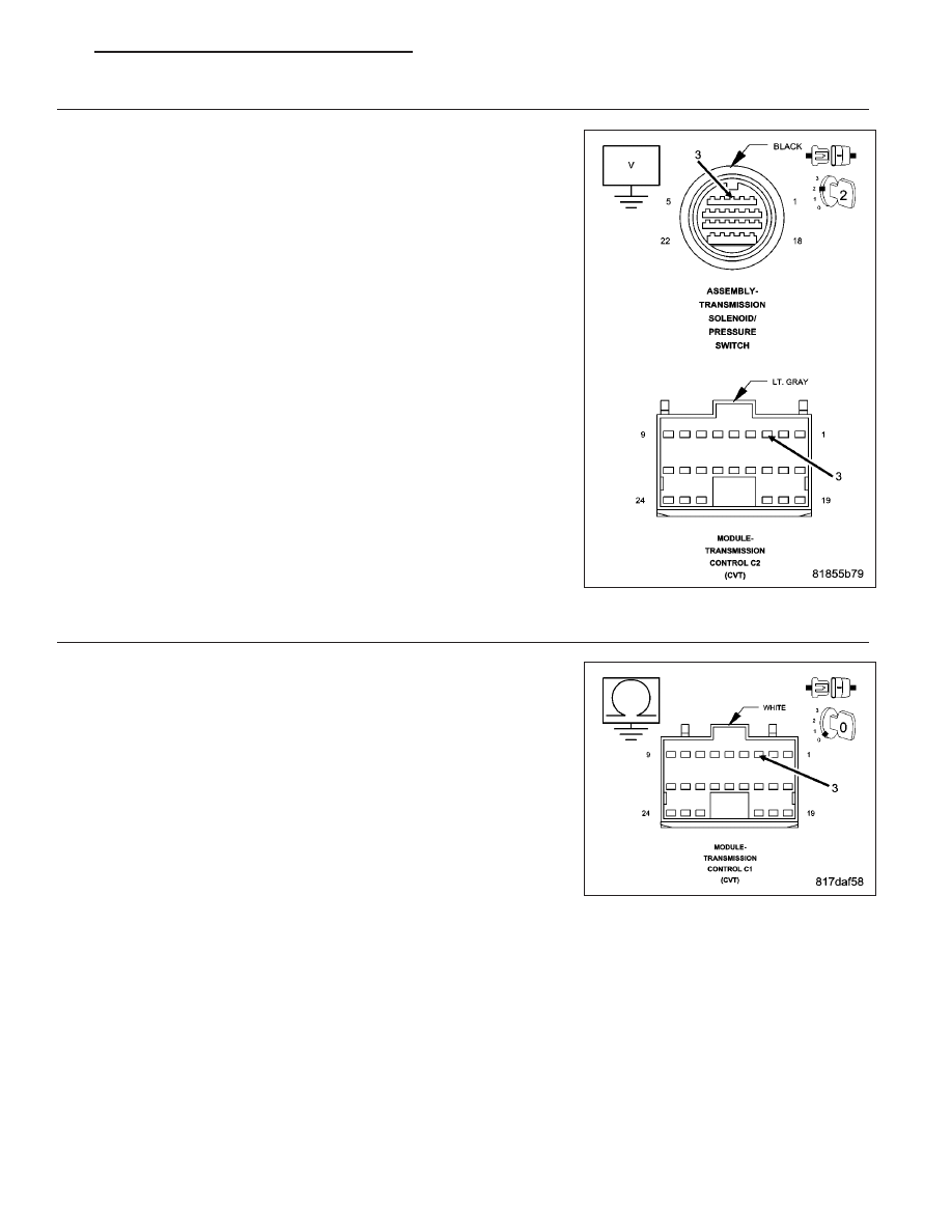
3.
CHECK THE (T59) TCC SOLENOID CONTROL CIRCUIT FOR A SHORT TO VOLTAGE
With the scan tool, stop the TCC Solenoid actuator.
Turn the ignition off to the lock position.
Disconnect the TCM C1 harness connector.
Ignition on, engine not running.
Measure the voltage of the (T59) TCC Solenoid Control circuit.
Is the voltage above 0.5 volts?
Yes
>> Repair the (T59) TCC Solenoid Control circuit for a short to
voltage.
Perform CVT VERIFICATION TEST. (Refer to 21 - TRANS-
MISSION/TRANSAXLE/AUTOMATIC - CVT - STANDARD
PROCEDURE)
No
>> Go To 4
4.
CHECK THE TCC SOLENOID
Turn the ignition off to the lock position.
Reconnect the Transmission Solenoid/Pressure Switch Assembly har-
ness connector.
Measure the resistance between ground and the (T59) TCC Solenoid
Control circuit in the TCM C1 harness connector.
Is the resistance between 3.0 and 9.0 ohms?
Yes
>> Using the schematics as a guide, check the Transmission
Control Module (TCM) terminals for corrosion, damage, or
terminal push out. Pay particular attention to all power and
ground circuits. Check for any Service Bulletins for possible
causes that may apply. If no problems are found, replace
the TCM per the Service Information.
Perform CVT VERIFICATION TEST. (Refer to 21 - TRANS-
MISSION/TRANSAXLE/AUTOMATIC - CVT - STANDARD
PROCEDURE)
No
>> Replace the TCC Solenoid (Valve Body) per the Service Information.
Perform CVT VERIFICATION TEST. (Refer to 21 - TRANSMISSION/TRANSAXLE/AUTOMATIC - CVT -
STANDARD PROCEDURE)
PM
AUTOMATIC - CVT-ELECTRICAL DIAGNOSTICS
21 - 255