Dodge Caliber. Manual - part 1225


  Index      Dodge     Dodge Caliber - service repair manual 2007 year


Search            


Content   ..  1223  1224  1225  1226   ..


Dodge Caliber. Manual - part 1225


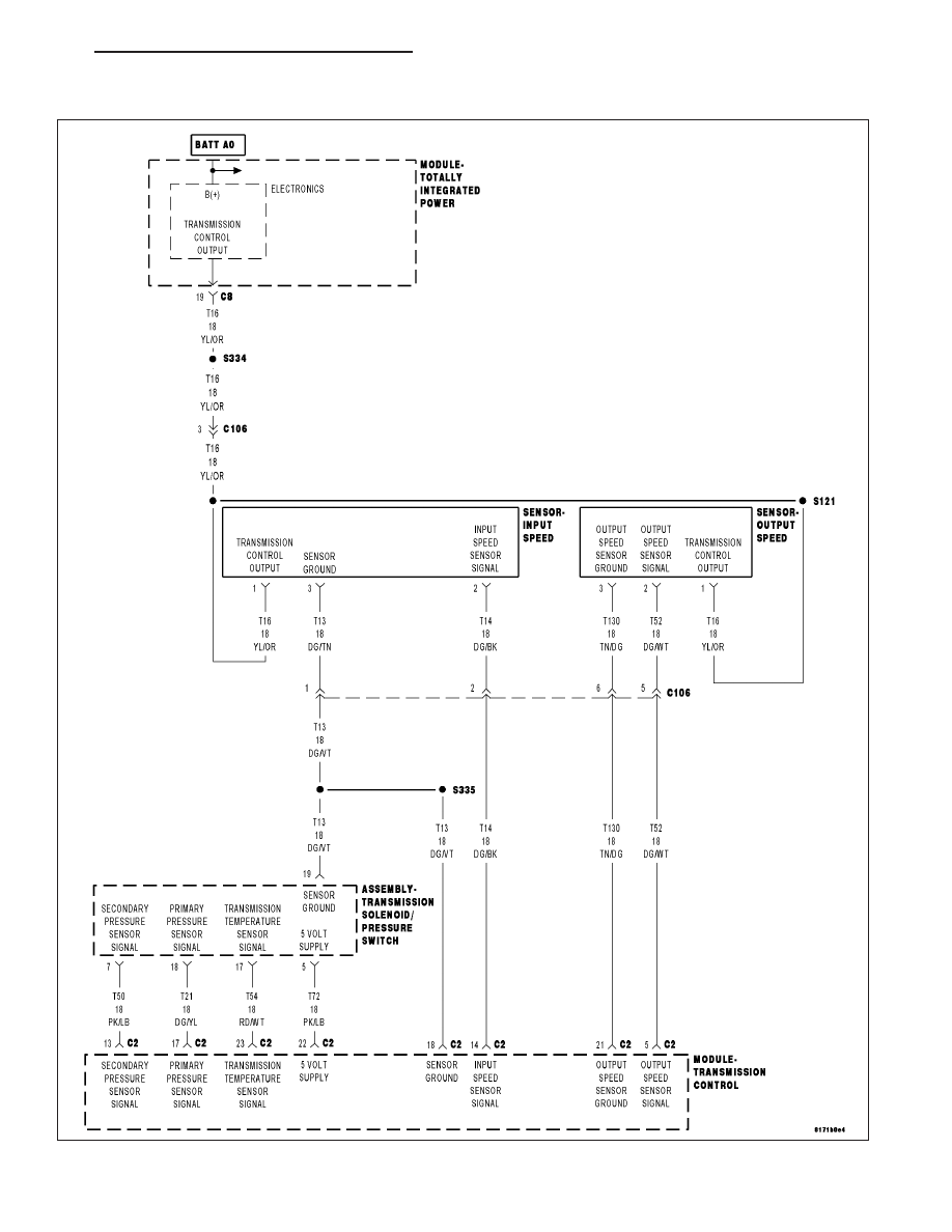
P0842-PRIMARY OIL PRESSURE SENSOR CIRCUIT LOW

For a complete wiring diagram Refer to Section 8W.

PM

AUTOMATIC - CVT-ELECTRICAL DIAGNOSTICS

21 - 199

Theory of Operation

The Transmission Control Module (TCM) monitors the input voltage from the primary pulley pressure sensor. When
the voltage is below a predetermined limit a DTC will set.

When Monitored:
Ignition on, system voltage between 9.0 and 16.0 volts.
Transmission temperature greater than -20° C (-4° F)
No active DTCs from the following:

Primary Oil Pressure Sensor High

Sensor ground

Set Condition:
When the monitored voltage drops below 0.09 volts for the period of 5 seconds.

Possible Causes

(T72) 5 VOLT SUPPLY CIRCUIT OPEN

(T21) PRIMARY PRESSURE SENSOR SIGNAL CIRCUIT OPEN

(T21) PRIMARY PRESSURE SENSOR SIGNAL CIRCUIT SHORT TO GROUND

PRIMARY PRESSURE SENSOR

TRANSMISSION CONTROL MODULE

Always perform the CVT Pre-Diagnostic Troubleshooting procedure before proceeding. (Refer to 21 -
TRANSMISSION/TRANSAXLE/AUTOMATIC - CVT - STANDARD PROCEDURE)

Diagnostic Test

1.

CHECK THE PRIMARY PRESSURE SENSOR VOLTAGE

With the scan tool, read the Primary Pulley Pressure Sensor voltage.

Is the voltage below 0.09 volts?

Yes

>> Go To 2

No

>> Go To 7

2.

CHECK THE (T72) 5 VOLT SUPPLY CIRCUIT

Turn the ignition off to the lock position.

Disconnect the Transmission Solenoid/Pressure Switch Assembly har-
ness connector.

Ignition on, engine not running.

Measure the voltage of the (T72) 5 Volt Supply circuit in the Transmis-
sion Solenoid/Pressure Switch Assembly harness connector.

Is the voltage 5.0 volts (± 0.2 volts)?

Yes

>> Go To 3

No

>> Go To 6

21 - 200

AUTOMATIC - CVT-ELECTRICAL DIAGNOSTICS

PM

3.

CHECK THE (T21) PRIMARY PRESSURE SENSOR SIGNAL CIRCUIT

Turn the ignition off to the lock position.

Disconnect the Transmission Solenoid/Pressure Switch Assembly har-
ness connector.

Ignition on, engine not running.

Connect a jumper wire between the (T21) Primary Pressure Sensor Sig-
nal circuit and the (T72) 5 Volt Supply circuit in the Transmission Sole-
noid/Pressure Switch Assembly harness connector.

With the scan tool, read the Primary Pulley Pressure Sensor voltage.

Is the voltage 5.0 volts (± 0.2 volts)?

Yes

>> Replace CV Transmission or replace the Primary Pressure

Sensor (Valve Body) per the Service Information.

Perform CVT VERIFICATION TEST. (Refer to 21 - TRANS-
MISSION/TRANSAXLE/AUTOMATIC - CVT - STANDARD
PROCEDURE)

No

>> Go To 4

4.

CHECK THE (T21) PRIMARY PRESSURE SENSOR SIGNAL CIRCUIT FOR AN OPEN

Turn the ignition off to the lock position.

Disconnect the TCM C2 harness connector.

Measure the resistance of the (T21) Primary Pressure Sensor Signal
circuit between the TCM C2 harness connector and the Transmission
Solenoid/Pressure Switch Assembly harness connector.

Is the resistance above 5.0 ohms?

Yes

>> Repair the (T21) Primary Pressure Sensor Signal circuit for

an open or high resistance.

Perform CVT VERIFICATION TEST. (Refer to 21 - TRANS-
MISSION/TRANSAXLE/AUTOMATIC - CVT - STANDARD
PROCEDURE)

No

>> Go To 5

PM

AUTOMATIC - CVT-ELECTRICAL DIAGNOSTICS

21 - 201

5.

CHECK THE (T21) PRIMARY PRESSURE SENSOR SIGNAL CIRCUIT FOR A SHORT TO GROUND

Measure the resistance between ground and the (T21) Primary Pres-
sure Sensor Signal circuit.

Is the resistance below 5.0 ohms?

Yes

>> Repair the (T21) Primary Pressure Sensor Signal circuit for

a short to ground.

Perform CVT VERIFICATION TEST. (Refer to 21 - TRANS-
MISSION/TRANSAXLE/AUTOMATIC - CVT - STANDARD
PROCEDURE)

No

>> Using the schematics as a guide, check the Transmission

Control Module (TCM) terminals for corrosion, damage, or
terminal push out. Pay particular attention to all power and
ground circuits. Check for any Service Bulletins for possible
causes that may apply. If no problems are found, replace
the TCM per the Service Information.

Perform CVT VERIFICATION TEST. (Refer to 21 - TRANS-
MISSION/TRANSAXLE/AUTOMATIC - CVT - STANDARD
PROCEDURE)

6.

CHECK THE (T72) 5 VOLT SUPPLY CIRCUIT FOR AN OPEN

While back probing, measure the voltage of the (T72) 5 Volt Supply cir-
cuit in Transmission Solenoid/Pressure Switch Assembly harness con-
nector.

Is the voltage 5.0 volts (± 0.2 volts)?

Yes

>> Repair the (T72) 5 Volt Supply circuit for an open or high

resistance.

Perform CVT VERIFICATION TEST. (Refer to 21 - TRANS-
MISSION/TRANSAXLE/AUTOMATIC - CVT - STANDARD
PROCEDURE)

No

>> Using the schematics as a guide, check the Transmission

Control Module (TCM) terminals for corrosion, damage, or
terminal push out. Pay particular attention to all power and
ground circuits. Check for any Service Bulletins for possible
causes that may apply. If no problems are found, replace
the TCM per the Service Information.

Perform CVT VERIFICATION TEST. (Refer to 21 - TRANSMISSION/TRANSAXLE/AUTOMATIC - CVT -
STANDARD PROCEDURE)

21 - 202

AUTOMATIC - CVT-ELECTRICAL DIAGNOSTICS

PM


Content   ..  1223  1224  1225  1226   ..