Content .. 1215 1216 1217 1218 ..
Dodge Caliber. Manual - part 1217
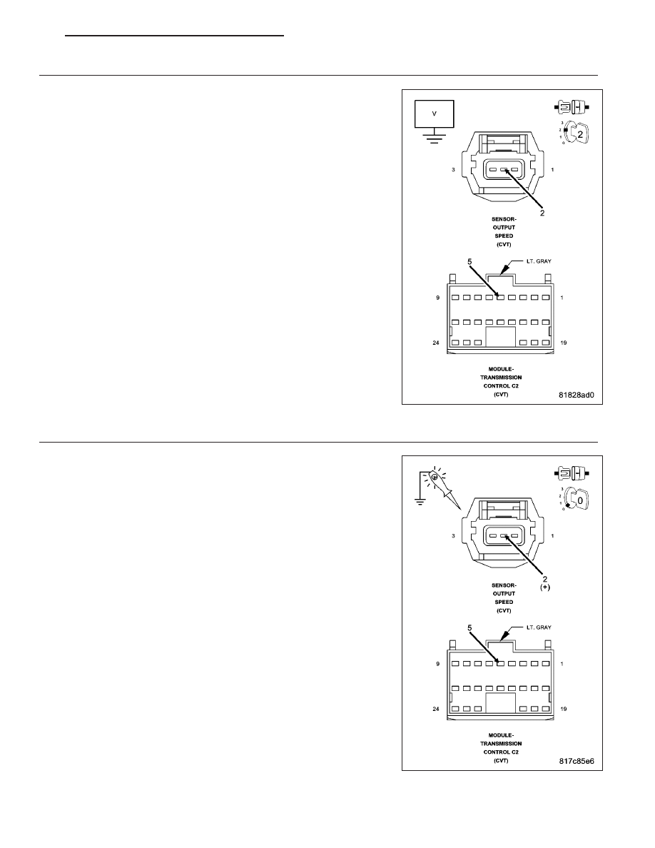
5.
CHECK THE (T52) OUTPUT SPEED SENSOR SIGNAL CIRCUIT FOR A SHORT TO VOLTAGE
Turn the ignition off to the lock position.
Disconnect the TCM C2 harness connector.
Ignition on, engine not running
Measure the voltage of the (T52) Output Speed Sensor Signal circuit.
Is the voltage above 0.2 volts?
Yes
>> Repair the (T52) Output Speed Sensor Signal circuit for a
short to voltage.
Perform CVT VERIFICATION TEST. (Refer to 21 - TRANS-
MISSION/TRANSAXLE/AUTOMATIC - CVT - STANDARD
PROCEDURE)
No
>> Using the schematics as a guide, check the Transmission
Control Module (TCM) terminals for corrosion, damage, or
terminal push out. Pay particular attention to all power and
ground circuits. Check for any Service Bulletins for possible
causes that may apply. If no problems are found, replace
the TCM per the Service Information.
Perform CVT VERIFICATION TEST. (Refer to 21 - TRANS-
MISSION/TRANSAXLE/AUTOMATIC - CVT - STANDARD
PROCEDURE)
6.
CHECK THE (T52) OUTPUT SPEED SENSOR SIGNAL CIRCUIT FOR AN OPEN (HIGH RESISTANCE)
Turn the ignition off to the lock position.
Disconnect the TCM C2 harness connector.
Connect a jumper wire between the (T52) Output Speed Sensor Signal
circuit and B(+) in the Output Speed Sensor harness connector.
Using a 12-volt test light connected to ground, check the (T52) Output
Speed Sensor Signal circuit in the TCM C2 harness connector.
NOTE: The test light must illuminate brightly. Compare the bright-
ness to that of a direct connection to the battery.
Does the test light illuminate brightly?
Yes
>> Go To 7
No
>> Repair the (T52) Output Speed Sensor Signal circuit for an
open or high resistance.
Perform CVT VERIFICATION TEST. (Refer to 21 - TRANS-
MISSION/TRANSAXLE/AUTOMATIC - CVT - STANDARD
PROCEDURE)
PM
AUTOMATIC - CVT-ELECTRICAL DIAGNOSTICS
21 - 167