Dodge Caliber. Manual - part 1201


  Index      Dodge     Dodge Caliber - service repair manual 2007 year


Search            


Content   ..  1199  1200  1201  1202   ..


Dodge Caliber. Manual - part 1201


SYNCHRONIZER

DISASSEMBLY

Place synchronizer in a clean shop towel and wrap. Press on inner hub. Carefully open up shop towel and remove
springs, balls, keys, hub, and sleeve.

CLEANING

CLEAN

Do not attempt to clean the blocking rings in solvent. The friction material will become contaminated. Place syn-
chronizer components in a suitable holder and clean with solvent. Air dry.

INSPECTION

INSPECT

Proper inspection of components involve:

Teeth, for wear, scuffed, nicked, burred, or broken teeth

Keys, for wear or distortion

Balls and springs, for distortion, cracks, or wear

If any of these conditions exist in these components, replace as necessary.
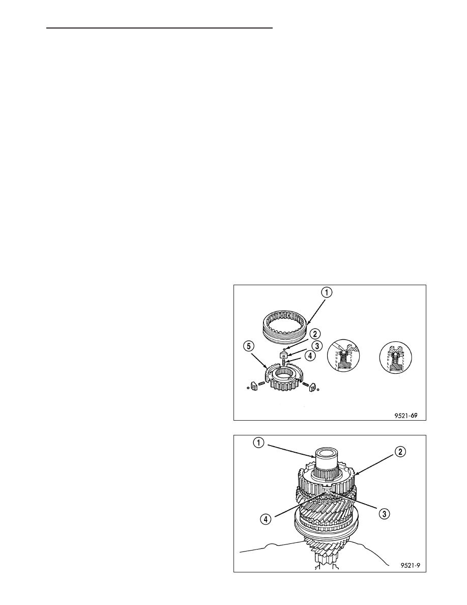
ASSEMBLY

1. Position synchronizer hub (5) onto a suitable hold-

ing fixture (input shaft). The synchronizer hubs (5)
are directional. The hubs must be installed with the
facing upward.

2. Install springs (4) into hub slot.

3. Insert key (3) into hub (2) and spring.

4. Apply petroleum jelly to the hole in the key. Insert

balls (4) into each key.

PM

T355 MANUAL TRANSAXLE

21 - 103

5. Slide sleeve (1) over the hub and depress balls as

you carefully slip the sleeve into position.

6. Line up stop ring tang over the keys in the hub,

install stop rings, center the keys (3) and balls (4)
by pushing on both stop rings.

21 - 104

T355 MANUAL TRANSAXLE

PM

SENSOR-VEHICLE SPEED

DESCRIPTION

VEHICLE SPEED SENSOR

The Vehicle Speed Sensor (VSS) is a hall effect sensor mounted above the transaxle differential. The sensor is
triggered by the ring gear teeth passing below it. The VSS pulse signal to the speedometer/odometer is monitored
by the PCM speed control circuitry to determine vehicle speed and to maintain speed control set speed.

REMOVAL

1. Open hood.

2. Remove the air cleaner housing. (Refer to 9 - ENGINE/AIR INTAKE SYSTEM/AIR CLEANER HOUSING -

REMOVAL)

3. Disconnect the speed sensor connector (1).

CAUTION: Clean area around speed sensor before removing to prevent dirt from entering the transaxle dur-
ing speed sensor removal.

4. Remove speed sensor retaining bolt.

5. Remove speed sensor from transaxle.

INSTALLATION

1. Using a NEW o-ring (3), install the speed sensor (2) to the transaxle.

2. Install the bolt and torque to 7 N·m (60 in. lbs.).

3. Connect speed sensor connector (1).

4. Install the air cleaner housing. (Refer to 9 - ENGINE/AIR INTAKE SYSTEM/AIR CLEANER HOUSING - INSTAL-

LATION)

PM

T355 MANUAL TRANSAXLE

21 - 105

AUTOMATIC - CVT-ELECTRICAL DIAGNOSTICS

TABLE OF CONTENTS

page

page

AUTOMATIC - CVT-ELECTRICAL DIAGNOSTICS

DIAGNOSIS AND TESTING

P128B-TCM POWER CONTROL CIRCUIT 2

LOW - TIPM . . . . . . . . . . . . . . . . . . . . . . . . . . . . . . 109

P128C-TCM POWER CONTROL CIRCUIT 2

HIGH - TIPM. . . . . . . . . . . . . . . . . . . . . . . . . . . . . . 112

P128D-TCM POWER CONTROL CIRCUIT 2

OPEN - TIPM . . . . . . . . . . . . . . . . . . . . . . . . . . . . . 115

P128E-TCM POWER CONTROL CIRCUIT 2

OVERCURRENT - TIPM . . . . . . . . . . . . . . . . . . . 118

P0219-ENGINE OVERSPEED . . . . . . . . . . . . . . . 121
P0571-BRAKE SWITCH 1 PERFORMANCE . . 123
P0602-CONTROL MODULE PROGRAMING

ERROR/NOT PROGRAMMED . . . . . . . . . . . . . . 125

P0610-ECU VEHICLE OPTIONS MISMATCH . 127
P0641-SENSOR REFERENCE VOLTAGE 1

CIRCUIT . . . . . . . . . . . . . . . . . . . . . . . . . . . . . . . . . 129

P0707-TRANSMISSION RANGE SENSOR

CIRCUIT LOW . . . . . . . . . . . . . . . . . . . . . . . . . . . . 133

P0708-TRANSMISSION RANGE SENSOR

CIRCUIT HIGH . . . . . . . . . . . . . . . . . . . . . . . . . . . 138

P0711-TRANSMISSION TEMPERATURE

SENSOR PERFORMANCE. . . . . . . . . . . . . . . . . 141

P0712-TRANSMISSION TEMPERATURE

SENSOR LOW. . . . . . . . . . . . . . . . . . . . . . . . . . . . 145

P0713-TRANSMISSION TEMPERATURE

SENSOR HIGH . . . . . . . . . . . . . . . . . . . . . . . . . . . 149

P0716-INPUT SPEED SENSOR 1 CIRCUIT

PERFORMANCE. . . . . . . . . . . . . . . . . . . . . . . . . . 153

P0717-INPUT SPEED SENSOR 1 CIRCUIT

NO SIGNAL . . . . . . . . . . . . . . . . . . . . . . . . . . . . . . 158

P0721-OUTPUT SPEED SENSOR CIRCUIT

PERFORMANCE. . . . . . . . . . . . . . . . . . . . . . . . . . 164

P0722-OUTPUT SPEED SENSOR CIRCUIT

NO SIGNAL . . . . . . . . . . . . . . . . . . . . . . . . . . . . . . 170

P0730-INCORRECT GEAR RATIO . . . . . . . . . . . 176
P0741-TORQUE CONVERTER CLUTCH

CIRCUIT PERFORMANCE . . . . . . . . . . . . . . . . . 177

P0746-LINE PRESSURE SOLENOID

PERFORMANCE. . . . . . . . . . . . . . . . . . . . . . . . . . 179

P0776-SECONDARY PRESSURE SOLENOID

STUCK OFF (HIGH PRESSURE) . . . . . . . . . . . 183

P0777-SECONDARY PRESSURE SOLENOID

STUCK ON (LOW PRESSURE). . . . . . . . . . . . . 189

P0826-UP/DOWN SHIFT SWITCH CIRCUIT . . 195
P0842-PRIMARY OIL PRESSURE SENSOR

CIRCUIT LOW . . . . . . . . . . . . . . . . . . . . . . . . . . . . 199

P0843-PRIMARY OIL PRESSURE SENSOR

CIRCUIT HIGH . . . . . . . . . . . . . . . . . . . . . . . . . . . 204

P0847-SECONDARY OIL PRESSURE

SENSOR CIRCUIT LOW . . . . . . . . . . . . . . . . . . . 208

P0848-SECONDARY OIL PRESSURE

SENSOR CIRCUIT HIGH . . . . . . . . . . . . . . . . . . 213

P0962-PRESSURE CONTROL SOLENOID A

CONTROL CIRCUIT LOW. . . . . . . . . . . . . . . . . . 217

P0963-PRESSURE CONTROL SOLENOID A

CONTROL CIRCUIT HIGH . . . . . . . . . . . . . . . . . 220

P0966-PRESSURE CONTROL SOLENOID B

CONTROL CIRCUIT LOW. . . . . . . . . . . . . . . . . . 224

P0967-PRESSURE CONTROL SOLENOID B

CONTROL CIRCUIT HIGH . . . . . . . . . . . . . . . . . 227

P161B-BATTERY DISCONNECT / TCM

INTERNAL . . . . . . . . . . . . . . . . . . . . . . . . . . . . . . . 231

P1661-SENSOR GROUND REFERENCE

CIRCUIT . . . . . . . . . . . . . . . . . . . . . . . . . . . . . . . . . 234

P1679-CALIBRATION NOT LEARNED . . . . . . . . 237
P167A-CALIBRATION MISMATCH . . . . . . . . . . . 239
P1702-PRIMARY OIL PRESSURE SENSOR /

SECONDARY OIL PRESSURE SENSOR
CORRELATION . . . . . . . . . . . . . . . . . . . . . . . . . . . 240

P1723-LOCK UP / SELECT CONTROL

CIRCUIT . . . . . . . . . . . . . . . . . . . . . . . . . . . . . . . . . 242

P1729-TRANSMISSION RATIO CONTROL

CIRCUIT . . . . . . . . . . . . . . . . . . . . . . . . . . . . . . . . . 246

P2769-TORQUE CONVERTER CLUTCH

CIRCUIT LOW . . . . . . . . . . . . . . . . . . . . . . . . . . . . 249

P2770-TORQUE CONVERTER CLUTCH

CIRCUIT HIGH . . . . . . . . . . . . . . . . . . . . . . . . . . . 253

U0001-CAN C BUS . . . . . . . . . . . . . . . . . . . . . . . . . 256
U0100-LOST COMMUNICATION WITH

ECM/PCM . . . . . . . . . . . . . . . . . . . . . . . . . . . . . . . . 257

U0121-LOST COMMUNICATION WITH

ANTILOCK BRAKE MODULE. . . . . . . . . . . . . . . 257

U0141-LOST COMMUNICATION WITH IPM

(FCM/TIPM) . . . . . . . . . . . . . . . . . . . . . . . . . . . . . . 257

U1146-LOST COMMUNICATION WITH

EXTERNAL MEMORY . . . . . . . . . . . . . . . . . . . . . 259

U1400-IMPLAUSIBLE TPS SIGNAL

RECEIVED . . . . . . . . . . . . . . . . . . . . . . . . . . . . . . . 265

U1401-IMPLAUSIBLE ENGINE SPEED

SIGNAL RECEIVED . . . . . . . . . . . . . . . . . . . . . . . 267

U1407-IMPLAUSIBLE ENGINE TORQUE

REQUEST SIGNAL RECEIVED . . . . . . . . . . . . . 269

U140F-IMPLAUSIBLE ENGINE VARIANT

DATA . . . . . . . . . . . . . . . . . . . . . . . . . . . . . . . . . . . . 271

U1410-IMPLAUSIBLE FCM VARIANT DATA . . . 273
U1424-IMPLAUSIBLE ENGINE TORQUE

SIGNAL RECEIVED . . . . . . . . . . . . . . . . . . . . . . . 274

U1425-IMPLAUSIBLE PEDAL POSITION

SIGNAL RECEIVED . . . . . . . . . . . . . . . . . . . . . . . 276

U1426-IMPLAUSIBLE TCC SLIP REQUEST

SIGNAL RECEIVED . . . . . . . . . . . . . . . . . . . . . . . 278

21 - 106

AUTOMATIC - CVT-ELECTRICAL DIAGNOSTICS

PM


Content   ..  1199  1200  1201  1202   ..