Dodge Caliber. Manual - part 1152


  Index      Dodge     Dodge Caliber - service repair manual 2007 year


Search            


Content   ..  1150  1151  1152  1153   ..


Dodge Caliber. Manual - part 1152


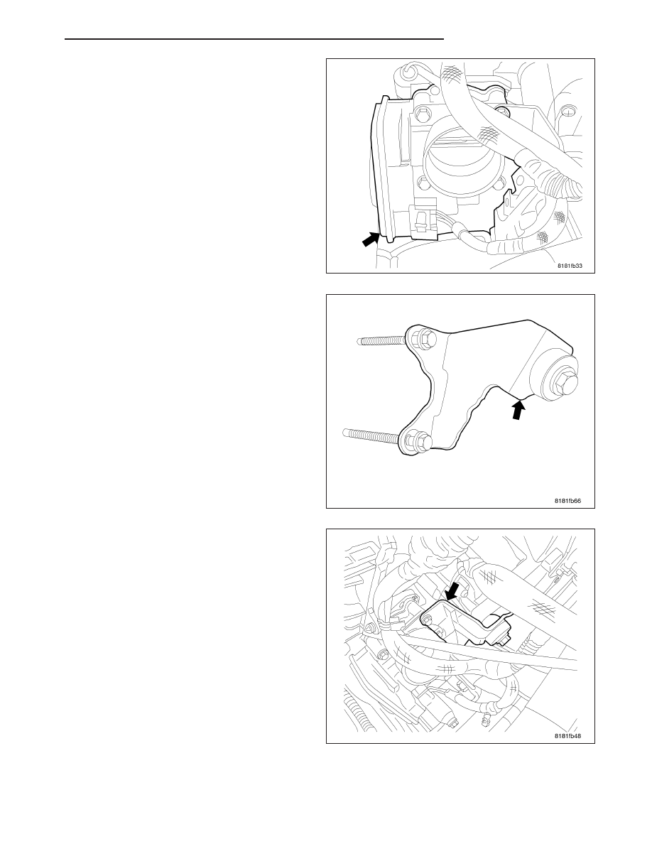
2. Position throttle body on intake manifold alignment

pins and install 2 mounting bolts. Do Not tighten
bolts at this time.

3. Install throttle body bracket.

4. Tighten throttle body bolts to 9 N·m (79.5 in. lbs.)

torque.

5. Throttle body bracket installed.

PM

FUEL INJECTION

14 - 81

6. Connect electrical connectors to throttle body.

7. Install air tube and connect wiring harness to air

tube.

8. Connect negative battery cable.

14 - 82

FUEL INJECTION

PM

MANIFOLD FLOW VALVE

OPERATION

The World Engine is equipped with an intake manifold flow control valve to promote maximum air/fuel atomization.
The valve restricts airflow, causing it to tumble or swirl. The tumbling action helps ensure that the fuel and air mix
thoroughly and burn faster. The intake manifold flow control valve and variable valve timing work together to
improve fuel economy, idle stability, and emissions.

The electrically controlled intake manifold flow control valve is located in the intake manifold at the cylinder head.
The intake manifold is constructed of composite material and divided into equal length runners. At the end of each
runner is an intake manifold flow control valve flap. The intake manifold flow control valve actuator controls the flaps
through a common shaft.

The intake manifold flow control valve actuator is a two-position torque motor that is pulse-width driven by the
GPEC1. The actuator is either energized to move the flaps out of the way to the wide-open position or de-energized
to move the flaps up, to a restricted position.

The intake manifold flow control valve actuator also contains a potentiometer feedback system to aid in diagnosis.
The potentiometer circuit reports the actual position of the intake manifold flow control valve flaps. The GPEC1
compares the actual position with the desired position to ensure that the system is functioning correctly. The intake
manifold flow control valve flaps are the mechanical components that restrict airflow to the intake ports. When the
valves are moved upward, airflow is restricted and tumble occurs. When the valves are flat against the manifold, the
full, unrestricted air charge flows to the intake ports.

It is energized under specific operating conditions: At high engine speeds (greater than 3600 rpm on the 1.8 and 2.0
liter or greater than 4000 rpm on the 2.4 liter) or at wide-open throttle, the intake manifold flow control valve actuator
is energized and the flaps move to the wide-open position, at lower engine speeds (less than 3600 rpm on the 1.8
and 2.0 liter or less than 4000 rpm on the 2.4 liter), the actuator is de-energized allowing the flaps to remain in the
restricted position. The flap is held at that position by the return spring.

REMOVAL

1. Disconnect negative battery cable.

2. Remove air tube,

PM

FUEL INJECTION

14 - 83

3. Disconnect electrical connector.

4. Remove 3 mounting screws.

5. Remove valve.

14 - 84

FUEL INJECTION

PM


Content   ..  1150  1151  1152  1153   ..