Content .. 1149 1150 1151 1152 ..
Dodge Caliber. Manual - part 1151
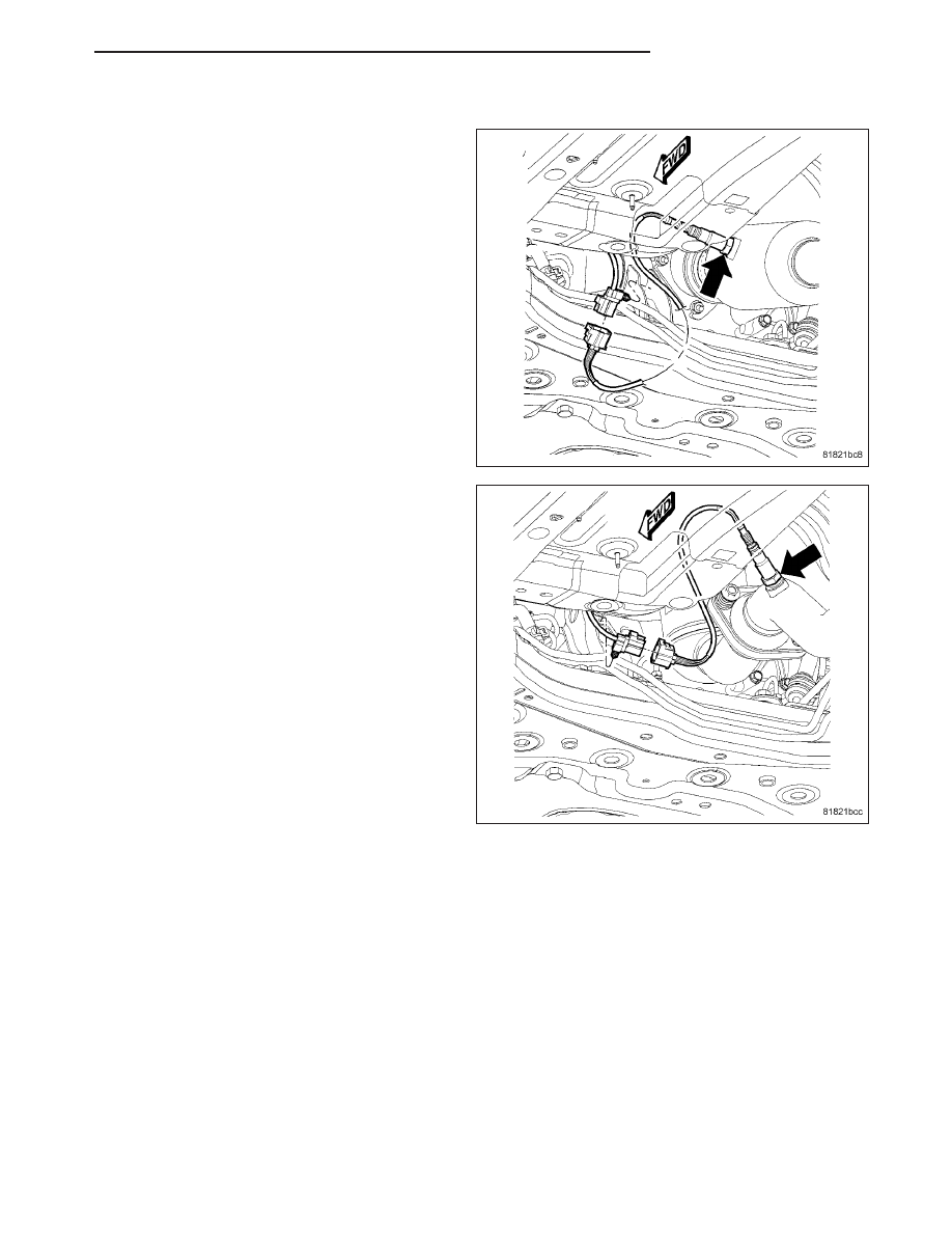
1/2 DOWNSTREAM
The downstream heated oxygen sensor threads into
the exhaust pipe behind the catalytic convertor.
1. After removing the sensor, the exhaust manifold
threads must be cleaned with an 18 mm X 1.5 +
6E tap. If reusing the original sensor, coat the sen-
sor threads with an anti-seize compound such as
Loctite
T
771-64 or equivalent. New sensors have
compound on the threads and do not require an
additional coating. Tighten the sensor to 28 N·m
(20 ft. lbs.) torque.
2. Install sensor using an oxygen sensor crow foot
wrench such as Snap-On tool YA8875 or equiva-
lent
3. Connect sensor electrical harness to clips along
body.
4. Connect electrical connector to sensor.
5. Lower vehicle.
6. Install the negative battery cable.
PM
FUEL INJECTION
14 - 77