Dodge Caliber. Manual - part 1116


  Index      Dodge     Dodge Caliber - service repair manual 2007 year


Search            


Content   ..  1114  1115  1116  1117   ..


Dodge Caliber. Manual - part 1116


MANIFOLD-EXHAUST

REMOVAL

1. Remove engine cover.

2. Remove clean air hose and air cleaner housing.

3. Disconnect negative cable from battery.

4. Disconnect throttle and speed control cables from

the throttle lever and bracket.

5. Disconnect MAP sensor electrical connector.

6. Remove fasteners securing power steering fluid

reservoir to cylinder head.

7. Remove coolant recovery container (Refer to 7 -

COOLING/ENGINE/COOLANT RECOVERY CON-
TAINER - REMOVAL).

8. Remove bolts attaching upper heat shield.

9. Remove upper heat shield.

10. Raise vehicle.

11. Disconnect exhaust pipe from manifold.

12. Remove engine wiring heat shield.

13. Remove manifold support bracket.

14. Remove lower exhaust manifold heat shield.

15. Disconnect oxygen sensor electrical connector.

16. Remove exhaust manifold lower retaining fasteners.

17. Lower vehicle and remove the upper exhaust manifold retaining fasteners.

18. Remove exhaust manifold from above/between the engine and cowl panel.

19. Remove and discard manifold gasket.

20. Mark prop shaft and differential for proper installation (if equipped).

21. Remove the rear prop shaft (if equipped) (Refer to 3 - DIFFERENTIAL & DRIVELINE/PROPELLER SHAFT -

REMOVAL).

22. Remove the two exhaust to maniverter (exhaust manifold with catalytic converter) bolts.

23. Unplug the down - stream O2 sensor connector.

24. Remove the exhaust system (Refer to 11 - EXHAUST SYSTEM/MUFFLER - REMOVAL).

25. Lower the vehicle on the hoist.

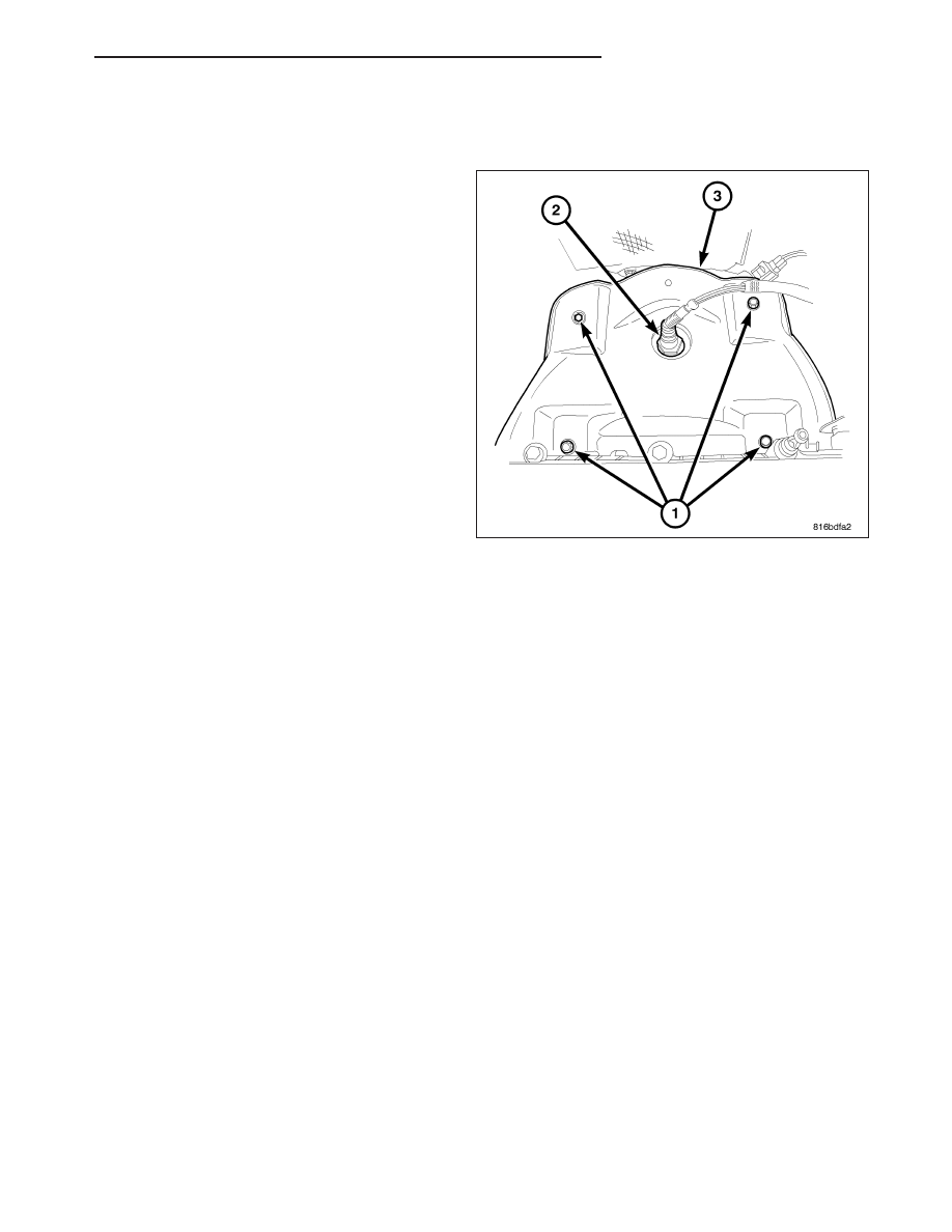
26. Unplug the up - stream O2 sensor connector.

27. Remove up - stream O2 sensor from the maniverter (exhaust manifold with catalytic converter) using o2 sensor

socket 8439 (2).

28. Remove the four maniverter heat shield bolts (1).

29. Remove the two retaining bolts and one nut from the maniverter side heat shield (3).

30. Remove the seven maniverter to head retaining bolts.

31. Slide the maniverter up and to the right, The support the maniverter (1) with the help of a bungie cord.

32. Raise the vehicle on the hoist.

33. Remove the four (1) engine to maniverter bracket bolts.

34. Remove the rear engine mount through bolt (2).

35. Remove the three front engine mount to frame bolts and the mount through bolt.

36. Remove the PTU mounting bolts.

37. Install a screw jack (2)on front engine mount bracket (1).

38. Raise the front of the engine until the rear mount has dropped (1,2).

39. Separate the PTU from the transaxle.

PM

ENGINE 2.4L WORLD

9 - 1751

40. Remove and discard old O-ring between Transmission and PTU

41. Roll the PTU (1) forward and down to remove.

CLEANING

1. Discard gasket (if equipped) and clean all surfaces of manifold and cylinder head.

INSPECTION

1. Inspect manifold gasket surfaces for flatness with straight edge. Surface must be flat within 0.15 mm per 300 mm

(0.006 in. per foot) of manifold length.

2. Inspect manifolds for cracks or distortion. Replace manifold as necessary.

INSTALLATION

1. Install a new exhaust manifold gasket. DO NOT APPLY SEALER.

2. Position exhaust manifold in place. Tighten fasteners, starting at center and progressing outward in both direc-

tions to 23 N·m (200 in. lbs.). Raise and lower vehicle for fastener access as necessary. Repeat tightening pro-
cedure until all fasteners are at specified torque.

3. Install exhaust manifold heat shields. Tighten bolts to 12 N·m (105 in. lbs.).

4. Install exhaust manifold support bracket.

5. Install engine wiring heat shield.

6. Connect oxygen sensor electrical connector.

7. Install exhaust pipe to manifold. Tighten fasteners to 28 N·m (250 in. lbs.).

8. Install coolant recovery container (Refer to 7 - COOLING/ENGINE/COOLANT RECOVERY CONTAINER -

INSTALLATION).

9. Install fasteners securing power steering fluid reservoir to cylinder head.

10. Connect MAP sensor electrical connector.

11. Connect throttle and speed control cables to the throttle lever and bracket.

12. Connect negative cable to battery.

13. Install clean air hose and air cleaner housing.

14. Roll the PTU in moving from front to back.

15. Rest the PTU on the frame while the engine and transaxle are raised back into position.

16. Lower screw jack until rear mount through bolt can be installed.

17. Install rear mount through bolt and torque bolt to 75 Nm (55 ft. lbs.).

18.

Install the transmission crossmember and bolts, torque to 75 Nm (55 ft. lbs.).

19. Install the through bolt at the front transmission mount and torque to 75 Nm (55 ft. lbs.)

20. Insure that the O-ring between the PTU and transaxle is in place.

21. Slide the PTU into place.

22. Install and torque PTU mounting bolts to 58 N-m (43 lbf-ft).

23. Lower the hoist.

24. Place the maniverter back into place and install the seven bolts.

25. Torque the maniverter bolts.

26. Install the maniverter side heat shield into place.

27. Install the two retaining bolts and one retaining nut.

28. Install the maniverter heat shield and the four retaining bolts.

29. Torque the maniverter heat shield bolts.

30. Using tool 8439 install the O2 sensor.

31. Install the air box.

32. Install engine trim cover.

33. Raise the vehicle on the hoist.

34. Install the maniverter to block bracket and four mounting bolts.

9 - 1752

ENGINE 2.4L WORLD

PM

35. Torque maniverter to block bracket mounting bolts.

36. Install the exhaust system (Refer to 11 - EXHAUST SYSTEM/MUFFLER - INSTALLATION).

37. Install the Prop shaft (Refer to 3 - DIFFERENTIAL & DRIVELINE/PROPELLER SHAFT - INSTALLATION).

38. install the right axle shaft (Refer to 3 - DIFFERENTIAL & DRIVELINE/HALF SHAFT - INSTALLATION).

39. Install the right front tire.

40. Fill PTU. (Refer to 21 - TRANSMISSION/TRANSAXLE/POWER TRANSFER UNIT - STANDARD PROCE-

DURE).

41. lower hoist

42. Connect battery cables.

43. Top off the fluids.

PM

ENGINE 2.4L WORLD

9 - 1753

COVER-TIMING CHAIN

REMOVAL

1. Remove engine cover.

2. Perform fuel pressure bleed procedure.

3. Remove air cleaner housing (Refer to 9 - ENGINE/AIR INTAKE SYSTEM/AIR CLEANER HOUSING -

REMOVAL).

4. Disconnect negative battery cable.

5. Drain cooling system

6. Remove coolant recovery bottle.

7. Remove windshield washer bottle.

8. Remove power steering reservoir and set aside.

9. Remove make up air hose.

10. Remove PCV hose.

11. Disconnect ignition coil electrical connectors.

12. Remove cylinder head cover (Refer to 9 - ENGINE/CYLINDER HEAD/CYLINDER HEAD COVER(S) -

REMOVAL).

13. Raise vehicle.

14. Remove right lower splash shield.

15. Set engine to TDC.

16. Remove accessory drive belt (Refer to 7 - COOLING/ACCESSORY DRIVE/DRIVE BELTS - REMOVAL).

17. Remove lower A/C compressor retaining bolts.

18. Remove A/C compressor lower bracket.

19. Remove accessory drive belt lower idler pulley.

20. Remove crankshaft pulley.

21. Remove water pump pulley.

22. Remove timing chain cover lower bolts.

23. Lower vehicle.

24. Remove power steering pump and set aside.

25. Support engine with a suitable jack.

26. Remove right engine mount.

27. Remove accessory drive belt upper idler pulley.

28. Remove right engine mount bracket.

29. Remove accessory drive belt tensioner.

30. Remove timing chain cover upper retaining bolts.

31. Remove timing chain cover.

INSTALLATION

1. Clean all sealing surfaces.

2. Apply RTV as shown at the cylinder head to block parting line.

3. Apply RTV as shown in the corner of the oil pan and block.

4. Apply 2mm bead of RTV as shown.

5. Install timing chain cover.

6. Install timing chain cover upper retaining bolts and torque bolts.

7. Install accessory drive belt tensioner.

8. Install right engine mount bracket and torque.

9. Install accessory drive belt upper idler pulley.

10. Install right engine mount and torque bolts.

9 - 1754

ENGINE 2.4L WORLD

PM


Content   ..  1114  1115  1116  1117   ..