Dodge Caliber. Manual - part 1080


  Index      Dodge     Dodge Caliber - service repair manual 2007 year


Search            


Content   ..  1078  1079  1080  1081   ..


Dodge Caliber. Manual - part 1080


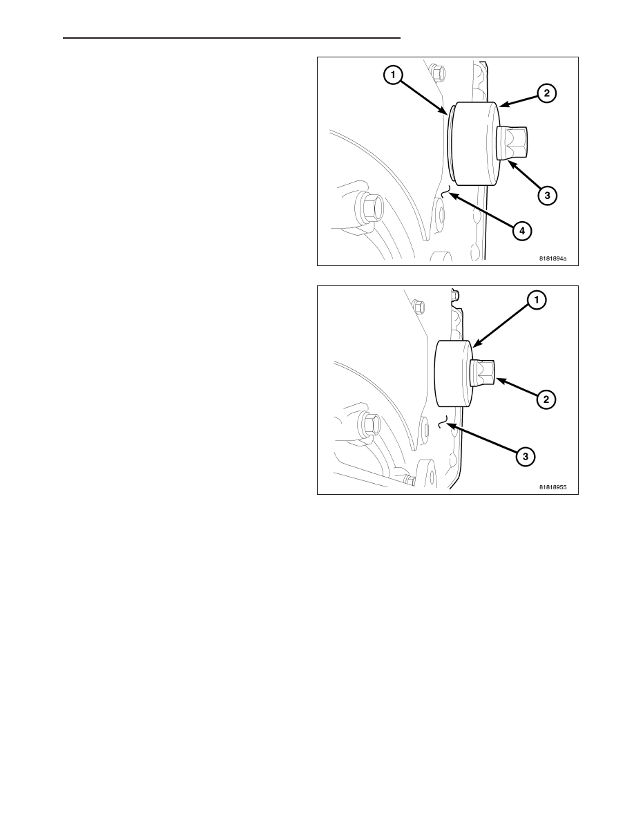
2. Install new seal (1) by using Seal installer 9506 (2)

and crankshaft damper bolt (3).

3. Press seal into front cover until Seal Installer 9506

(1) seats against timing chain cover (3).

4. Remove seal installer 9506 (1).

5. Install crankshaft vibration damper (Refer to 9 -

ENGINE/ENGINE BLOCK/VIBRATION DAMPER -
INSTALLATION.

PM

ENGINE 2.0L WORLD

9 - 1607

SEAL-CRANKSHAFT OIL REAR

REMOVAL

1. Remove transaxle

2. Remove flex plate bolts and discard.

3. Remove flex plate (1).

4. Insert a 3/16 flat bladed screwdriver (7) between

the dust lip (8) and the metal case (4) of the crank-
shaft seal (1). Angle the screwdriver through the
dust lip against metal case of the seal. Pry out
seal.

CAUTION: Do not permit the screwdriver blade to
contact crankshaft seal surface. Contact of the
screwdriver blade against crankshaft edge (cham-
fer) is permitted.

9 - 1608

ENGINE 2.0L WORLD

PM

INSTALLATION

CAUTION: If a burr or scratch is present on the
crankshaft edge (chamfer), cleanup with 400 grit
sand paper to prevent seal damage during instal-
lation of new seal.

NOTE: When installing seal, no lube on seal is
needed.

1. Place Special Tool 9509 (3) Seal Guide on crank-

shaft.

2. Position seal (2) over guide tool. Guide tool should

remain on crankshaft during installation of seal.
Ensure that the lip of the seal is facing towards the
crankcase during installation.

3. Drive the seal into the block using Special Tool

9706 (1) and handle C-4171 (4) until the tool bot-
toms out against the block.

4. Install flex plate (1). Install new flex plate bolts and

torque to 95 N·m (70 ft. lbs.).

5. Install transaxle. Refer to TRANSMISSION/TRANS-

AXLE - INSTALLATION for procedure.

PM

ENGINE 2.0L WORLD

9 - 1609

PISTON & ROD-CONNECTING

DESCRIPTION

The pistons are made of a cast aluminum alloy. The pistons have pressed-in pins attached to forged connecting
rods. The pistons pin is offset 0.8 mm (0.0314 in.) towards the thrust side of the piston. The connecting rods are a
cracked cap design and are not repairable. The pistons with rings and connecting rods are serviced as an assembly.

STANDARD PROCEDURE

PISTON TO CYLINDER BORE FITTING

NOTE: Pistons and cylinder bores should be mea-
sured at normal room temperature, 21°C (70°F).

Piston and cylinder wall must be clean and dry. Piston
diameter should be measured 90 degrees to piston
pin (1).

1. Measurement should be taken approximately 16

mm (0.629 in.) from the bottom of the skirt (2) as
shown in.

NOTE: Correct piston to bore clearance must be
established in order to assure quiet and economi-
cal operation.

2. Cylinder bores should be measured halfway down

the cylinder bore and transverse (measurement
location B) to the engine crankshaft center line
shown in. Refer to for Engine Specifications (Refer
to 9 - ENGINE - SPECIFICATIONS).

REMOVAL

NOTE: Pistons, rings, and rods are serviced as an assembly.

CAUTION: All four piston/rod assemblies must be replaced as a set or engine damage may result.

1. Remove engine (Refer to 9 - ENGINE - REMOVAL).

2. Separate engine from transaxle.

3. Remove cylinder head (Refer to 9 - ENGINE/CYLINDER HEAD - REMOVAL).

9 - 1610

ENGINE 2.0L WORLD

PM


Content   ..  1078  1079  1080  1081   ..