Dodge Caliber. Manual - part 1046


  Index      Dodge     Dodge Caliber - service repair manual 2007 year


Search            


Content   ..  1044  1045  1046  1047   ..


Dodge Caliber. Manual - part 1046


43. Disconnect electronic throttle control electrical connector.

44. Disconnect map sensor electrical connector.

45. Disconnect vacuum lines at intake.

46. Remove intake manifold retaining bolts.

47. Remove upper radiator hose retaining bolts.

48. Remove intake manifold.

49. Remove coolant outlet manifold and set aside.

50. Remove ground strap at right rear of cylinder head.

51. Remove oxygen sensor from maniverter (AWD).

52. Remove maniverter heat shields (AWD).

53. Remove maniverter retaining bolts (AWD).

54. Remove maniverter from cylinder head and reposition out of the way (AWD).

55. Remove camshafts (Refer to 9 - ENGINE/CYLINDER HEAD/CAMSHAFT(S) - REMOVAL).

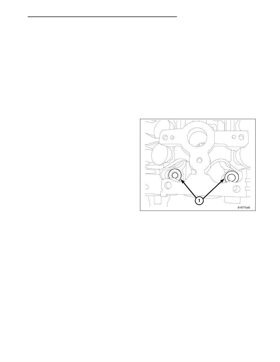
NOTE: All of the cylinder head bolts have captured
washersEXCEPTthe front two (1).

56. Remove cylinder head bolts.

57. Remove cylinder head from engine block.

58. Inspect and clean cylinder head and block sealing

surfaces. Refer to Cleaning and Inspection in this
section for procedures.

NOTE: Ensure cylinder head bolt holes in the
block are clean, dry (free of residual oil or cool-
ant), and threads are not damaged.

CLEANING

To ensure engine gasket sealing, proper surface preparation must be performed, especially with the use of alumi-
num engine components and multi-layer steel cylinder head gaskets.

NOTE: Multi-Layer Steel (MLS) head gaskets require a scratch free sealing surface.

Remove all gasket material from cylinder head and block (Refer to 9 - ENGINE - STANDARD PROCEDURE). Be
careful not to gouge or scratch the aluminum head sealing surface.

Clean all engine oil passages.

INSPECTION

NOTE: Replacement cylinder heads will come complete with valves, seals, springs, retainers, keepers, lash
buckets, and camshafts.

PM

ENGINE 1.8L WORLD

9 - 1471

1.

Cylinder head must be flat within 0.1 mm (0.004

in.).

2.

Inspect camshaft bearing journals for scoring.

3. Remove carbon and varnish deposits from inside of

valve guides with a reliable guide cleaner.

4. Using a small hole gauge and a micrometer, mea-

sure valve guides in 3 places top (1), middle (2),
and bottom (3). (Refer to 9 - ENGINE - SPECIFI-
CATIONS) Replace guides if they are not within
specification.

5. Check valve guide height.

6. Prior to installing cylinder head, the cylinder block

should be checked for flatness (Refer to 9 -
ENGINE/ENGINE BLOCK - INSPECTION).

INSTALLATION - CYLINDER HEAD

NOTE: Ensure cylinder head bolt holes in the
block are clean, dry (free of residual oil or cool-
ant), and threads are not damaged.

NOTE: The Cylinder head bolts should be exam-
ined BEFORE reuse. If the threads are necked
down, the bolts should be replaced.

Necking can be checked by holding a scale or straight
edge against the threads. If all the threads do not con-
tact the scale (2), the bolt should be replaced.

9 - 1472

ENGINE 1.8L WORLD

PM

CAUTION: Always replace the variable valve timing
filter screen (3) when servicing the head gasket or
engine damage could result.

1. Replace the variable valve timing filter screen (3).

2. Place two pea size dots of RTV (1) on cylinder

block as shown.

3. Position the new cylinder head gasket on engine

block with the part number facing up. Ensure gas-
ket is seated over the locating dowels in block.

4. Place two pea size dots of RTV (1) on cylinder

head gasket as shown.

NOTE: The head must be installed within 15 min-
utes before the RTV skins.

5. Position cylinder head onto engine block.

PM

ENGINE 1.8L WORLD

9 - 1473

NOTE: The front two cylinder head bolts do not
have captured washers. The washers must be
installed with the bevel up towards the bolt head.

6. Install washers (1) for the front two cylinder head

bolts.

7. Before installing the bolts, the threads should be

lightly coated with engine oil.

8. Install the cylinder head bolts and torque in the

sequence shown above.

First: All to 30 N·m (25 ft. lbs.)

Second: All to 61 N·m (50 ft. lbs.)

Third: All to 61 N·m (45 ft. lbs.)

Fourth: All an additional 90°

CAUTION: Do not use a torque wrench for the
Fourth step.

9. Install camshafts. (Refer to 9 - ENGINE/CYLINDER

HEAD/CAMSHAFT(S) - INSTALLATION).

10. Install cylinder head cover (Refer to 9 - ENGINE/

CYLINDER HEAD/CYLINDER HEAD COVER -
INSTALLATION).

11. Install maniverter/exhaust manifold to cylinder head. Torque fasteners to 34 N·m (25 ft.lbs.).

12. Install heat shields.Torque fasteners to 9 N·m ( ).

13. Install oxygen sensor in maniverter.

14. Install ground strap at right rear of cylinder head.

9 - 1474

ENGINE 1.8L WORLD

PM


Content   ..  1044  1045  1046  1047   ..