Dodge Caliber. Manual - part 102


  Index      Dodge     Dodge Caliber - service repair manual 2007 year


Search            


Content   ..  100  101  102  103   ..


Dodge Caliber. Manual - part 102


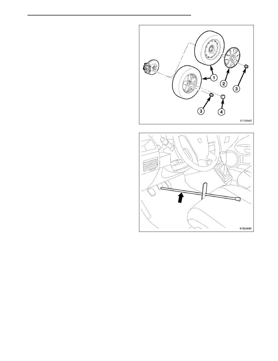
4. Install the tire and wheel assembly (1) (Refer to 22

- TIRES/WHEELS - INSTALLATION). Install and
tighten the wheel mounting nuts (3) to 135 N·m
(100 ft. lbs.).

5. Slowly rotate the rear wheel and verify that the

brake drum lightly drags on the shoes.

6. Lower the vehicle.

7. Remove the brake pedal holder.

8. Bleed the wheel cylinder as necessary. (Refer to 5

- BRAKES - STANDARD PROCEDURE)

9. Road test the vehicle to make sure the brakes

operate correctly.

PM

BRAKES - BASE

5 - 109

PARKING BRAKE

DESCRIPTION

The parking brakes consist of the following compo-
nents:

Hand-operated park brake lever (6)

Parking brake cables (one each side) (3)

Actuation levers and struts

Duo-servo parking brake assembly (rear disc
only)

All vehicles are equipped with a center-mounted,
hand-operated parking brake lever mounted between
the front seats. A bent nail tensioner is built into the
equalizer mounted on the end of the lever’s output
cable.

There is an individual parking brake cable for each
rear wheel that joins a parking brake cable equalizer,
attached to the parking brake lever, to the rear parking
brakes. The parking brake cables are made of flexible
steel cable. Both drum rear brakes and disc rear
brakes use the same parking brake cable configura-
tion, but the cables are different.

On vehicles equipped with rear drum brakes, the rear wheel service brakes also act as the vehicle’s parking brakes.
The rear drum brake shoes, when acting as parking brakes, are mechanically operated using an internal actuating
lever and strut connected to the flexible steel parking brake cable.

The parking brakes on vehicles equipped with rear disc brakes consist of a small duo-servo brake assembly
mounted to the disc brake caliper adapter including two shoes, an actuating lever and strut, as well as the attaching
springs and clips. This parking brake application uses the same operating cable configuration as the drum brake
equipped vehicles, but uses different cables.

The hat (center) section (2) of each rear disc brake
rotor (1) serves as the braking surface (drum) for the
parking brakes.

5 - 110

BRAKES - BASE

PM

CABLE-PARKING BRAKE

REMOVAL

NOTE: Before proceeding, (Refer to 5 - BRAKES - WARNING) (Refer to 5 - BRAKES - CAUTION).

NOTE: The procedure below applies to either of the two rear parking brake cables.

1. Disconnect and isolate the battery negative cable from its post on the battery.

2. Block the tire and wheel assemblies so the vehicle does not move once the vehicle parking brake lever is

released.

3. Remove the center console. (Refer to 23 - BODY/

INTERIOR/CENTER CONSOLE - REMOVAL)

4. Release and lower the parking brake lever (5).

5. Loosen the adjusting nut on the lever’s output

cable taking tension off parking brake cables.

6. Remove the parking brake cables (3) from the

parking brake cable equalizer (2).

7. Remove the rear seat cushion.

PM

BRAKES - BASE

5 - 111

8. Fold the rear carpeting forward (1) to expose the

parking brake cables (4) at the end of the rear
floor.

9. Install the box end of a

1

2

inch (13 mm) wrench (2)

over the retainer for either the right (3) or left (5)
parking brake cable. Push the wrench onto the
retainer until the retainer fingers are collapsed.
From under the carpeting, grasp the parking brake
cable housing and pull the cable straight out of the
bracket attached to the floor.

10. Raise and support the vehicle. (Refer to LUBRICATION & MAINTENANCE/HOISTING - STANDARD PROCE-

DURE)

11. Remove the wheel mounting nuts (3), then the

rear tire and wheel assembly (1).

12. Access and remove the parking brake shoes.

(Refer to 5 - BRAKES/PARKING BRAKE/SHOES
- REMOVAL)

13. Remove the hair pin (1) securing the parking

brake cable (2) to the brake support plate (3).

14. Pull the parking brake cable from the support

plate and hole in trailing link.

5 - 112

BRAKES - BASE

PM


Content   ..  100  101  102  103   ..