Dodge Caliber. Manual - part 96


  Index      Dodge     Dodge Caliber - service repair manual 2007 year


Search            


Content   ..  94  95  96  97   ..


Dodge Caliber. Manual - part 96


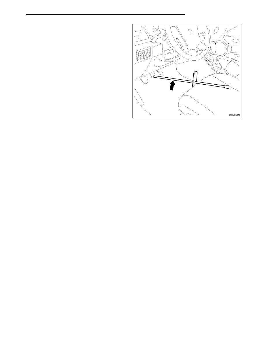
3. Remove the brake pedal holder.

4. Bleed the affected brake line(s). (Refer to 5 -

BRAKES - STANDARD PROCEDURE)

5. Road test the vehicle to ensure proper operation of

the brakes.

PM

BRAKES - BASE

5 - 85

ROTOR

DIAGNOSIS AND TESTING

BRAKE ROTOR

Any servicing of the rotor requires extreme care to maintain the rotor within service tolerances to ensure proper
brake action.

Excessive runout or wobble in a rotor can increase pedal travel due to piston knock-back. This increases guide pin
sleeve wear due to the tendency of the caliper to follow the rotor wobble.

When diagnosing a brake noise or pulsation, the machined disc braking surface should be inspected.

BRAKING SURFACE INSPECTION

Light braking surface scoring and wear is acceptable. If heavy scoring or warping is evident, the rotor must be
refaced or replaced. (Refer to 5 - BRAKES/HYDRAULIC/MECHANICAL/ROTORS - STANDARD PROCEDURE).

Excessive wear and scoring of the rotor can cause improper lining contact on the rotor’s braking surface. If the
ridges on the rotor are not removed before new brake shoes are installed, improper wear of the shoes will result.

If a vehicle has not been driven for a period of time, the rotor’s braking surface will rust in the areas not covered by
the brake shoes at that time. Once the vehicle is driven, noise and chatter from the disc brakes can result when the
brakes are applied.

Some discoloration or wear of the rotor surface is normal and does not require resurfacing when linings are
replaced. If cracks or burned spots are evident, the rotor must be replaced.

ROTOR MINIMUM THICKNESS

Measure rotor thickness (1) at the center of the brake
pad contact surface. Replace the rotor if it is worn
below minimum thickness or if machining the rotor will
cause its thickness to fall below specifications.

5 - 86

BRAKES - BASE

PM

CAUTION: Do not machine the rotor if it will cause the rotor to fall below minimum thickness.

On front rotors, Minimum thickness specifications (2)
are cast on the rotor’s unmachined surface on the
inside of the rotor (1). Limits can also be found in this
component’s

specification

table.

(Refer

to

5

-

BRAKES/HYDRAULIC/MECHANICAL/ROTOR

-

SPECIFICATIONS)

On rear rotors, Minimum thickness specifications (3)
are cast into the rotor’s unmachined surface on the
outside of the rotor (1). This area also shows the max-
imum thickness specifications (2) for the hat section of
the rotor. Limits can also be found in this component’s
specification table. (Refer to 5 - BRAKES/HYDRAU-
LIC/MECHANICAL/ROTOR - SPECIFICATIONS)

PM

BRAKES - BASE

5 - 87

ROTOR THICKNESS VARIATION

Thickness variation in a rotor’s braking surface can
result in pedal pulsation, chatter and surge. This can
also be caused by excessive runout in the rotor or the
hub.

Rotor thickness variation measurements should be
made in conjunction with measuring runout. Measure
thickness of the brake rotor (2) at 12 equal points
around the rotor braking surface with a micrometer (1)
at a radius approximately 25 mm (1 inch) from edge of
rotor. If thickness measurements vary beyond the
specification listed in the specification table (Refer to 5
-

BRAKES/HYDRAULIC/MECHANICAL/ROTOR

-

SPECIFICATIONS), the rotor should be refaced or
replaced. (Refer to 5 - BRAKES/HYDRAULIC/ME-
CHANICAL/ROTOR - STANDARD PROCEDURE).

ROTOR RUNOUT

On-vehicle rotor runout is the combination of the indi-
vidual runout of the hub face and the runout of the
brake rotor (hub runout can be measured separately).
To measure rotor runout on the vehicle:

1. Raise and support the vehicle. (Refer to LUBRICA-

TION & MAINTENANCE/HOISTING - STANDARD
PROCEDURE)

2. Remove the tire and wheel assembly. (Refer to 22

- TIRES/WHEELS - REMOVAL)

3. Install standard wheel mounting nuts, flat side to

rotor, on all the wheel studs (2). Progressively
tighten the nuts in a crisscross pattern to 135 N·m
(100 ft. lbs.).

4. Mount Dial Indicator (1), Special Tool C-3339A,

with Wheel, Special Tool 25w, or equivalent, to the
knuckle. Position the dial indicator wheel to contact
the rotor braking surface approximately 10 millime-
ters from the outer edge of the rotor (3).

5. Slowly rotate the brake rotor checking lateral

runout, marking the low and high spots. Record these measurements.

6. Check and record the runout on the opposite side of the rotor in the same fashion, marking the low and high

spots.

5 - 88

BRAKES - BASE

PM


Content   ..  94  95  96  97   ..