Dodge Caliber. Manual - part 91


  Index      Dodge     Dodge Caliber - service repair manual 2007 year


Search            


Content   ..  89  90  91  92   ..


Dodge Caliber. Manual - part 91


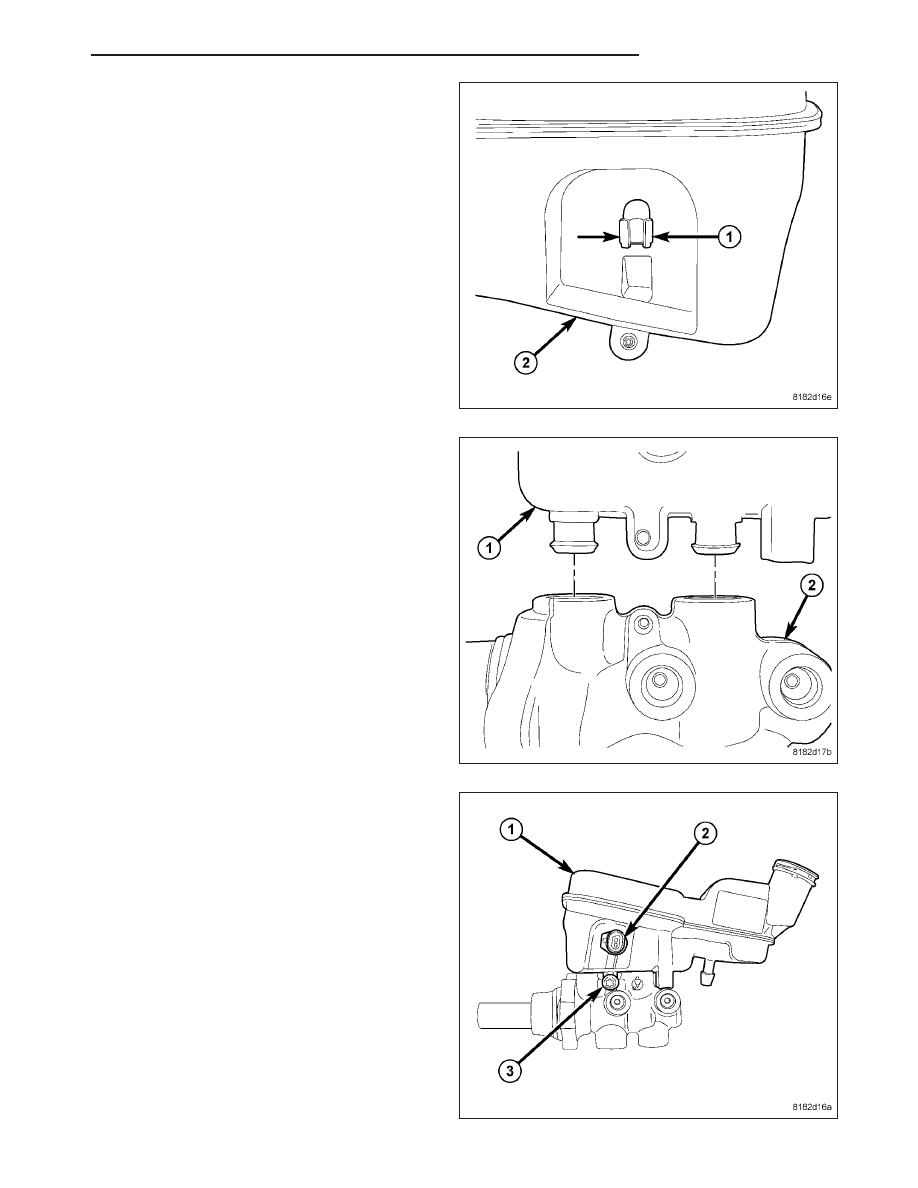
2. If the reservoir is being replaced, align the brake

fluid level switch with its mounting hole on the left
side of the master cylinder brake fluid reservoir.
Push the switch into the fluid reservoir until the
switch retaining tabs (1) are expanded on the other
side of the reservoir (2), locking it in place.

3. Lubricate the reservoir mounting area with fresh

clean brake fluid. Place the reservoir (1) in position
over the grommet seals in the master cylinder (2).
Slide the reservoir into the grommet seals by firmly
pressing

down

on

the

fluid

reservoir.

Once

installed, make sure fluid reservoir is touching the
top of both grommet seals.

4. Install the fluid reservoir mounting screw (3).

Tighten the screw to 5.5 N·m (48 in. lbs.).

5. Thoroughly bleed the master cylinder before install-

ing it. (Refer to 5 - BRAKES/HYDRAULIC/ME-
CHANICAL/MASTER

CYLINDER

-

STANDARD

PROCEDURE)

6. Install the master cylinder. (Refer to 5 - BRAKES/

HYDRAULIC/MECHANICAL/MASTER CYLINDER -
INSTALLATION)

PM

BRAKES - BASE

5 - 65

INSTALLATION

LEFT-HAND-DRIVE WITH ABS

NOTE: The master cylinder must be bled before installing it on the vehicle.

1. Bench bleed the master cylinder. (Refer to 5 - BRAKES/HYDRAULIC/MECHANICAL/MASTER CYLINDER -

STANDARD PROCEDURE)

2. Wipe the face of the power brake booster clean where the vacuum seal on the rear of the master cylinder comes

in contact when it’s installed. Do not get any cleaner or debris inside the booster.

CAUTION: When installing a master cylinder on
the vehicle, a NEW vacuum seal (2) MUST be
installed on the master cylinder mounting flange
(1).

3. If the master cylinder does not have a new vacuum

seal (2) on the mounting flange (1), remove it.
Install a NEW vacuum seal on the master cylinder
mounting flange making sure the seal fits squarely
in its groove.

CAUTION: If resistance is met during master cylinder insertion into power brake booster, the master cylin-
der push rod may not be lined up with the booster push rod. Remove the master cylinder, realign and insert
it again.

4. Line the master cylinder mounting holes up with the mounting studs on the power brake booster. Ensure the

master cylinder piston push rod lines up with the booster push rod, then carefully slide the master cylinder into
the power brake booster until it contacts the face of the booster.

5. Install two NEW master cylinder mounting nuts (3).

Tighten each nut to 25 N·m (18 ft. lbs.).

5 - 66

BRAKES - BASE

PM

6. If equipped with a manual transaxle and a new res-

ervoir is being installed, using an appropriate cut-
ting tool, cut the clutch actuator port at the center
of the “V” groove (2) opening the hydraulic clutch
port (1). Discard the severed plug (3).

7. If equipped with a manual transaxle, slide the

clutch actuator hose (2) onto the reservoir port (1).
Install the hose clamp just past the upset bead on
the port.

8. Connect the primary (1) and secondary (2) brake

tubes to the master cylinder outlet ports. Tighten
the tube nuts to 17 N·m (150 in. lbs.).

PM

BRAKES - BASE

5 - 67

9. Connect the wiring harness connector (1) to the

brake fluid level switch (2).

10. Connect the negative (ground) cable on the bat-

tery.

11. Fill the master cylinder reservoir to the proper

level. (Refer to 5 - BRAKES/HYDRAULIC/ME-
CHANICAL/FLUID - STANDARD PROCEDURE)

WARNING: Be certain a firm brake pedal is
achieved prior to attempting to operate the vehi-
cle. If a firm brake pedal cannot be achieved,
bleed the brake hydraulic system and check for
leaks. (Refer to 5 - BRAKES - STANDARD PROCE-
DURE)

12. Road test the vehicle to ensure proper operation

of the brakes.

LEFT-HAND-DRIVE WITHOUT ABS

NOTE: The proportioning valves are not identical
and cannot be interchanged. The proportioning
valve that threads into the primary port (3) has
M10 x 1 threads going into the master cylinder (1).
The proportioning valve that threads into the sec-
ondary port (2) has M12 x 1 threads going into the
master cylinder (1).

1. If removed, install the proportioning valves (2, 3) in

their master cylinder ports. Tighten the proportion-
ing valves to 30 N·m (22 ft. lbs.).

NOTE: The master cylinder must be bled before installing it on the vehicle.

2. Bench bleed the master cylinder. (Refer to 5 - BRAKES/HYDRAULIC/MECHANICAL/MASTER CYLINDER -

STANDARD PROCEDURE)

3. Wipe the face of the power brake booster clean where the master cylinder seal comes in contact when it’s

installed. Do not get any cleaner or debris inside the booster.

5 - 68

BRAKES - BASE

PM


Content   ..  89  90  91  92   ..