Dodge Caliber. Manual - part 64
C2208-AWD ECU INTERNAL
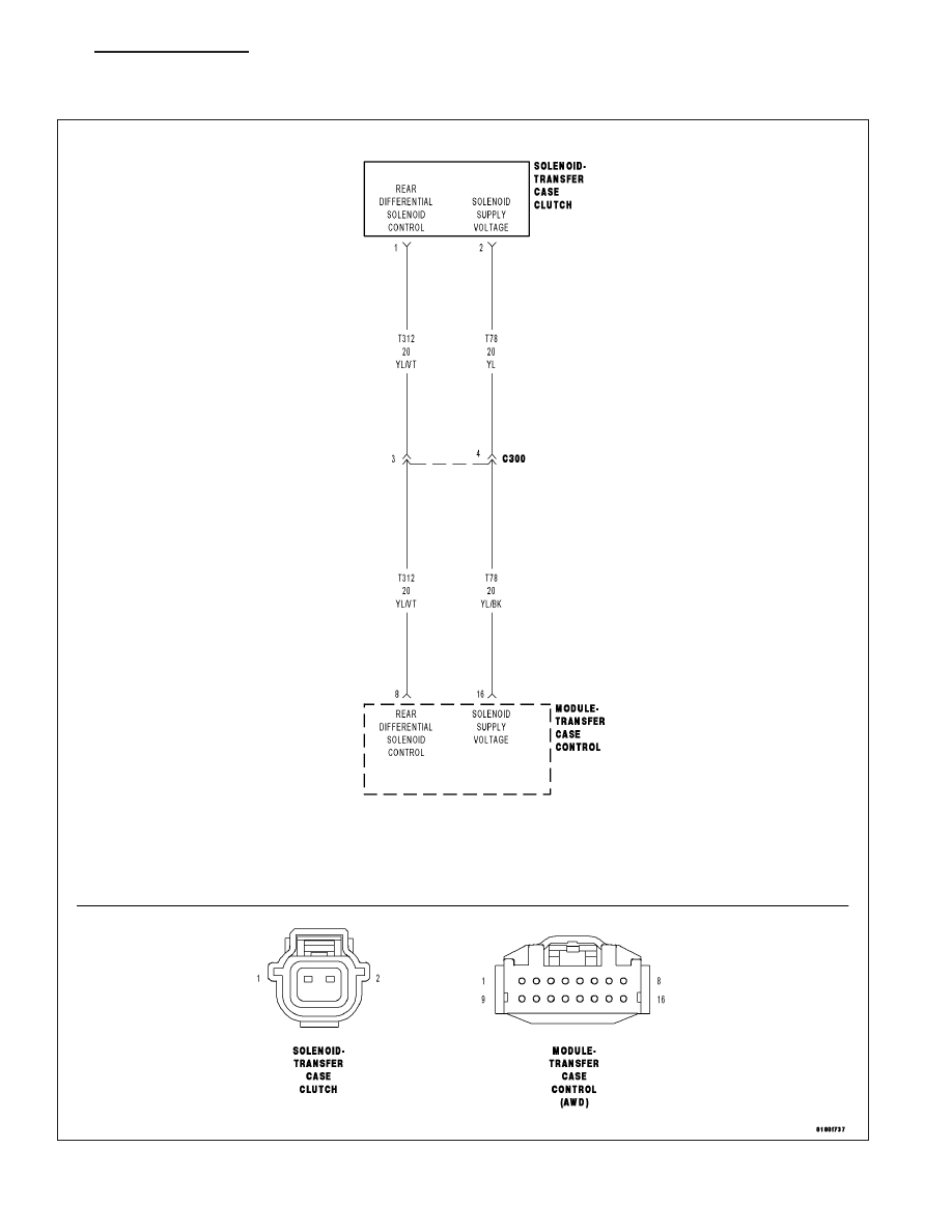
For a complete wiring diagram Refer to Section 8W
PM
CLUTCH-ELECTRONICALLY CONTROLLED-ELECTRICAL DIAGNOSTICS
3 - 131
|
|
|
C2208-AWD ECU INTERNAL For a complete wiring diagram Refer to Section 8W PM CLUTCH-ELECTRONICALLY CONTROLLED-ELECTRICAL DIAGNOSTICS 3 - 131 |