Dodge Nitro. Manual - part 921


  Index      Dodge     Dodge Nitro - service repair manual 2007 year


Search            


Content   ..  919  920  921  922   ..


Dodge Nitro. Manual - part 921


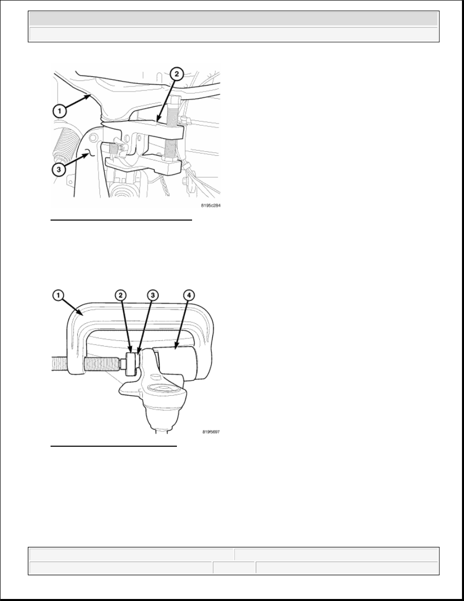
Fig. 20: Upper Ball Joint Separation 
Courtesy of CHRYSLER LLC 

6. Remove the upper ball joint nut.  

7. Separate the upper ball joint from the knuckle using special tool 9360 separator (2).  

8. Lower the control arm enough to install the press tool. 

Fig. 21: Clevis Bushing Removal 
Courtesy of CHRYSLER LLC 

9. Press the bushing (3) out using special tools C-4212F (Press) (1), 9956 (receiver) (4) and 9653-1 (driver) 

(2).  

NOTE:

Extreme pressure lubrication must be used on the threaded portions of the 
tool. This will increase the longevity of the tool and insure proper 
operation during the removal and installation process.


2007 Dodge Nitro R/T 

2007 SUSPENSION Suspension - Nitro


BUSHINGS-LOWER CONTROL ARM 

Fig. 22: LCA Bushing Removal 
Courtesy of CHRYSLER LLC 

1. Remove the lower control arm. See REMOVAL.  

2. Secure the control arm in a vise. 

3. Press the bushing (4) out using special tools C-4212F (Press) (1), 9334-5 (Receiver) (2) and 9603-3 

(Driver) (5).  

BUSHINGS-STABILIZER BAR 

1. Raise vehicle on hoist.  

2. Remove the stabilizer bushing clamps.  

3. Remove the stabilizer bushings from the stabilizer bar.  

INSTALLATION 

BUSHINGS-LOWER CONTROL ARM 

NOTE:

Extreme pressure lubrication must be used on the threaded portions of the 
tool. This will increase the longevity of the tool and insure proper 
operation during the removal and installation process.

NOTE:

Suspension components with rubber/urethane bushings should be tightened 
with the full weight of the vehicle at normal ride height. It is important to have 
the springs supporting the full weight of the vehicle when the fasteners are 
torqued. If springs are not at their normal ride position, vehicle ride comfort 
could be affected and premature bushing wear may occur.


2007 Dodge Nitro R/T 

2007 SUSPENSION Suspension - Nitro


Fig. 23: LCA Bushing Install 
Courtesy of CHRYSLER LLC 

1. Install the new lower control arm bushings (3) into the lower control arm (4) using tools C-4212F (Press) 

(1), 9603-1 (driver) (2) and 9969-1 (receiver) (5) making sure the receiver cup is properly centered for the 
bushing to be pressed in to the proper depth.  

2. Remove the control arm from the vise.  

3. Install the lower control arm. See INSTALLATION.  

4. Perform a wheel alignment. See STANDARD PROCEDURE.  

BUSHINGS-STABILIZER BAR 

1. Install the stabilizer bushings to the stabilizer bar.  

2. Install the stabilizer bushing clamps. Tighten the nuts to 149 N.m (110 ft.lbs.).  

3. Lower the vehicle.  

BUSHINGS-CLEVIS BRACKET 

NOTE:

Extreme pressure lubrication must be used on the threaded portions of the tool. 
This will increase the longevity of the tool and insure proper operation during 
the removal and installation process.

NOTE:

Suspension components with rubber/urethane bushings should be tightened 
with the full weight of the vehicle at normal ride height. It is important to have 
the springs supporting the full weight of the vehicle when the fasteners are 
torqued. If springs are not at their normal ride position, vehicle ride comfort 
could be affected and premature bushing wear may occur.

NOTE:

Suspension components with rubber/urethane bushings should be tightened 
with the full weight of the vehicle at normal ride height. It is important to have 


2007 Dodge Nitro R/T 

2007 SUSPENSION Suspension - Nitro


Fig. 24: Clevis Bushing Install 
Courtesy of CHRYSLER LLC 

1. Install the new clevis bracket bushing (4) into the lower control arm (3) using special tools C-4212F 

(Press) (1), 9957-2 (Depth Gauge) (2), 9957-1 (driver) (5).  

2. Install the upper ball joint to the knuckle and tighten the nut to 41 N.m (30 ft.lbs.) plus an additional 90° 

turn.  

3. Install the clevis bolt to the lower control arm and tighten the bolt to 150 N.m (110 ft.lbs.).  

4. Install the stabilizer link lower bolt to the control arm and tighten the bolt to 102 N.m (75 ft.lbs.).  

5. Install the wheel speed sensor. Refer to INSTALLATION .  

6. Install the disc brake rotor. Refer to INSTALLATION .  

7. Install the tire and wheel assembly. Refer to STANDARD PROCEDURE .  

8. Lower the vehicle.  

HUB/BEARING 

REMOVAL 

HUB/BEARING 

1. Raise and support the vehicle.  

2. Remove the tire and wheel assembly. 

the springs supporting the full weight of the vehicle when the fasteners are 
torqued. If springs are not at their normal ride position, vehicle ride comfort 
could be affected and premature bushing wear may occur.

NOTE:

Extreme pressure lubrication must be used on the threaded portions of the tool. 
This will increase the longevity of the tool and insure proper operation during 
the removal and installation process.


2007 Dodge Nitro R/T 

2007 SUSPENSION Suspension - Nitro


Content   ..  919  920  921  922   ..