Dodge Nitro. Manual - part 898


  Index      Dodge     Dodge Nitro - service repair manual 2007 year


Search            


Content   ..  896  897  898  899   ..


Dodge Nitro. Manual - part 898


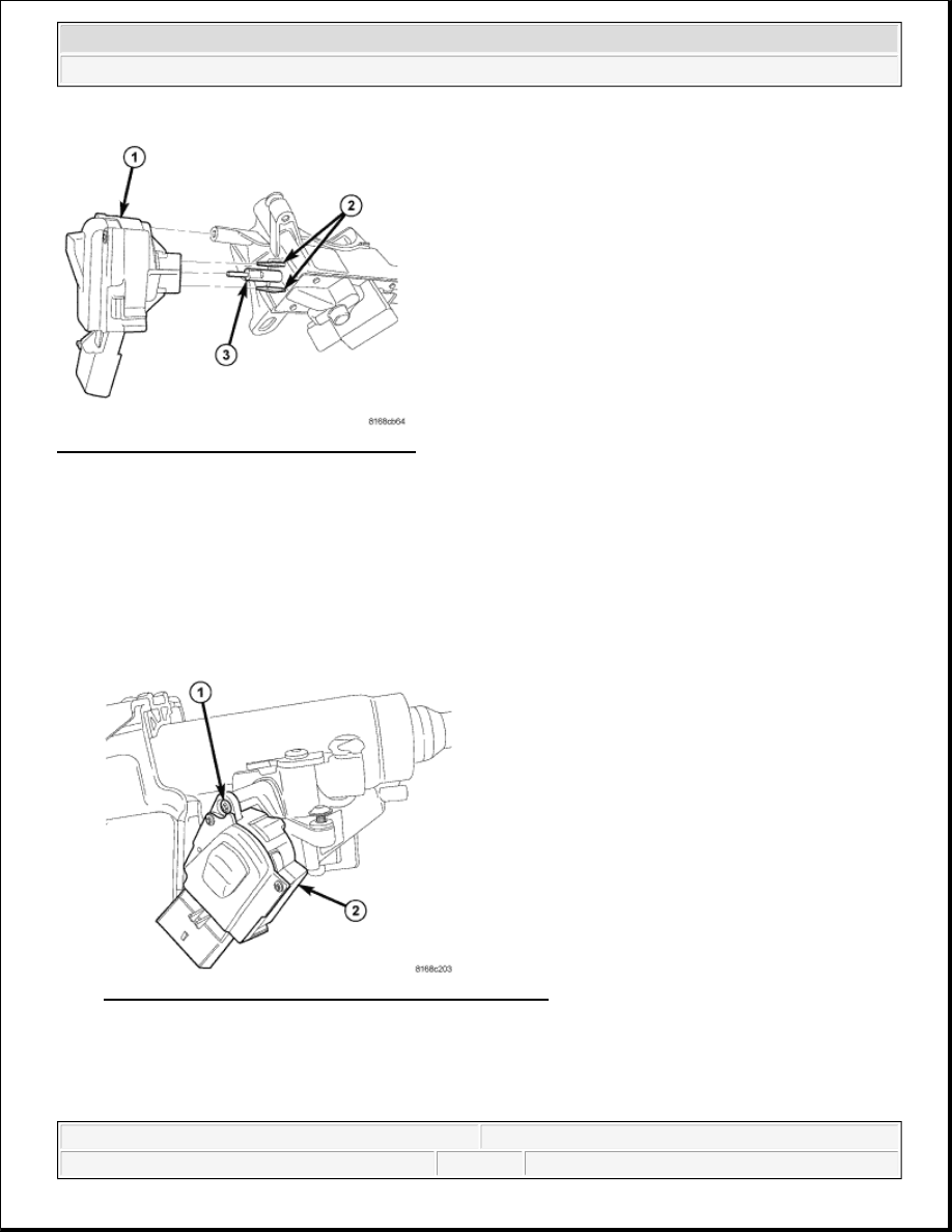
Fig. 29: Ignition Switch Removal/Installation 
Courtesy of CHRYSLER LLC 

1. Ensure the ignition module is in the RUN position and the actuator shaft in the lock housing is in the 

RUN position.  

2. Align the ignition module with the pin (3), actuator shaft and retaining tabs (2) located on the lock 

cylinder housing. Carefully install the module, snapping it into place over the retaining tabs. 

Fig. 30: Identifying Ignition Module & Mounting Screw 
Courtesy of CHRYSLER LLC 

3. Install the ignition module (2) mounting screw (1). Tighten the screw to 2 N.m (18 in. lbs.). 

NOTE:

Ignition module must be installed prior to lock housing installation on column. 
Otherwise, the tilt lever will obstruct installation of ignition switch.


2007 Dodge Nitro R/T 

2007 STEERING Steering System - Nitro


Fig. 31: Identifying Screws & Lock Cylinder Housing 
Courtesy of CHRYSLER LLC 

4. Position the lock cylinder housing in the RUN position.  

5. Align the lock cylinder housing (2) with the steering column.  

6. Install the two screws (1) fastening the lock cylinder housing (2) to the column. Tighten the screws to 12 

N.m (110 in. lbs.). 

Fig. 32: Access Hole For Lock Cylinder Removal 
Courtesy of CHRYSLER LLC 

7. Place the actuator in the lock cylinder housing to the RUN position (if not already there).  

8. Insert the key into the key cylinder and turn the key cylinder to the RUN position.  

9. Align the retaining tab on the key cylinder with the slot in the top of the lock cylinder housing. 

NOTE:

Ignition module needs to be installed on lock cylinder housing before 
housing installation to clear tilt lever.


2007 Dodge Nitro R/T 

2007 STEERING Steering System - Nitro


10. Slide the key cylinder into the lock cylinder housing until the key cylinder retaining tab locks the cylinder 

into place.  

11. Rotate the key back and forth (OFF to START), then remove and reinstall it, making sure the key 

cylinder and lock cylinder housing operate properly. 

Fig. 33: Identifying Screw, SKREEM/WCM & Lock Cylinder Housing 
Courtesy of CHRYSLER LLC 

12. Slide the ring of the SKREEM/WCM (2) over the lock cylinder housing (3) and engage the retainer 

fingers in the recesses formed on the lock cylinder housing.  

13. Install the screw (1) fastening the SKREEM/WCM (2) to the lock cylinder housing (3). Tighten the screw 

to 2.5 N.m (22 in. lbs.). 

Fig. 34: Installing Steering Column Control Module (SCCM) 
Courtesy of CHRYSLER LLC 

14. Install the Steering Column Control Module (SCCM) (3) and all components removed to access it. Refer 


2007 Dodge Nitro R/T 

2007 STEERING Steering System - Nitro


to INSTALLATION .  

15. Check operation of all steering column mounted components.  

INTERMEDIATE SHAFT 

REMOVAL 

STEERING INTERMEDIATE SHAFT - 4.0L 

1. Disconnect the negative battery cable.  

2. Remove knee blocker cover and knee blocker, refer to REMOVAL . 

3. Lock the steering wheel with the tires in the straight ahead position. 

Fig. 35: Identifying Lower Column Pinch Bolt & Steering Coupler 
Courtesy of CHRYSLER LLC 

4. Remove the lower column pinch bolt (2).  

5. Lower the steering coupler (1) shaft from the column. 

NOTE:

The steering column on vehicles with an automatic transmission may not 
be equipped with an internal locking shaft that allows the ignition key 
cylinder to be locked with the key. Alternative methods of locking the 
steering wheel for service will have to be used.


2007 Dodge Nitro R/T 

2007 STEERING Steering System - Nitro


Content   ..  896  897  898  899   ..