Dodge Nitro. Manual - part 888


  Index      Dodge     Dodge Nitro - service repair manual 2007 year


Search            


Content   ..  886  887  888  889   ..


Dodge Nitro. Manual - part 888


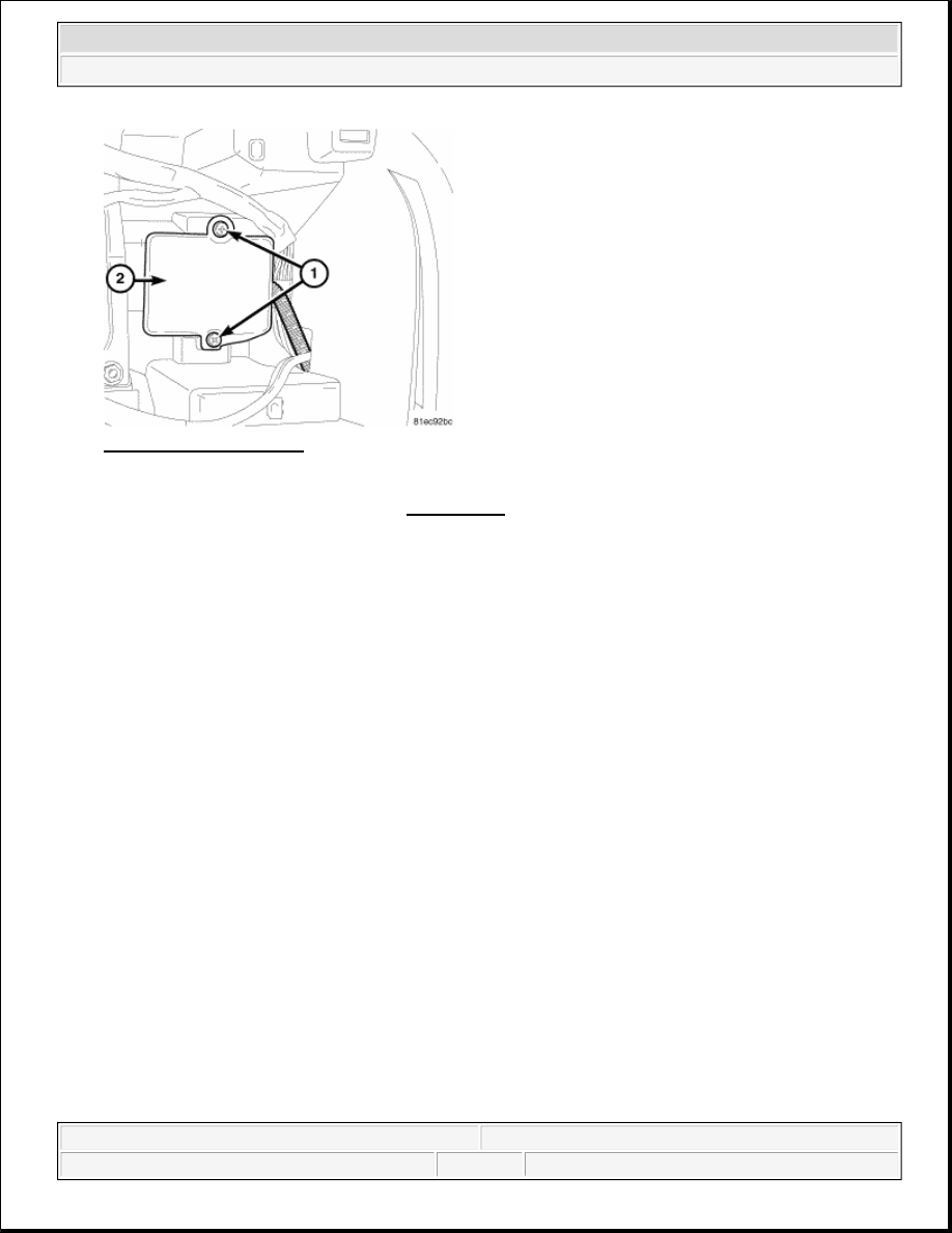
Fig. 28: Antenna Module 
Courtesy of CHRYSLER LLC 

7. Remove the instrument cluster, Refer to REMOVAL . 

8. Remove the remote start antenna coaxial cable from mounting clips, if equipped.  

9. Remove the screws (1) from remote start antenna module (2) and remove from instrument panel 

assembly.  

INSTALLATION 

INSTALLATION 

NOTE:

During removal of the remote start antenna note the routing location of the 
coaxial cable.

WARNING:

To avoid serious or fatal injury on vehicles equipped with airbags, disable 
the Supplemental Restraint System (SRS) before attempting any steering 
wheel, steering column, airbag, Occupant Classification System (OCS), 
seat belt tensioner, impact sensor, or instrument panel component 
diagnosis or service. Disconnect and isolate the battery negative (ground) 
cable, then wait two minutes for the system capacitor to discharge before 
performing further diagnosis or service. This is the only sure way to 
disable the SRS. Failure to take the proper precautions could result in 
accidental airbag deployment.


2007 Dodge Nitro R/T 

2007 ENGINE Starting - Service Information - Nitro


Fig. 29: Antenna Module 
Courtesy of CHRYSLER LLC 

1. Install the remote start antenna module (2), and screws (1) to instrument panel assembly. Tighten screws 

to 2.5 N.m (22 in. lbs.).  

2. Install the instrument cluster. Refer to INSTALLATION .  

3. Route the remote start coaxial cable in the position noted during the removal procedure.  

4. Install the remote start antenna coaxial cable to mounting clips, if equipped. 

Fig. 30: Identifying Mounting Bracket, Screw, Sentry Key Remote Entry Module (SKREEM), Start 
Antenna Coaxial Cable Connector, Instrument Panel Wire Harness Connector & Lock Cylinder
 
Courtesy of CHRYSLER LLC 

5. Connect remote start antenna coaxial cable connector (4) to the Sentry Key REmote Entry Module 

(SKREEM) (3) (also known as the Sentry Key Immobilizer Module/SKIM or the Wireless Control 
Module/WCM).  

6. Position the SKREEM onto the steering column ignition lock housing with the antenna ring oriented 


2007 Dodge Nitro R/T 

2007 ENGINE Starting - Service Information - Nitro


around the lock cylinder (6).  

7. Install and tighten the screw (2) that secures the SKREEM mounting bracket to the boss on the top of the 

ignition lock housing. Tighten the screw to 2 N.m (20 in. lbs.).  

8. Reconnect the instrument panel wire harness connector (5) to the SKREEM connector receptacle.  

9. Reinstall the right multi-function switch onto the integral mounting bracket (1) on the right side of the 

clockspring. Refer to INSTALLATION .  

10. Reconnect the battery negative cable.  

NOTE:

On vehicles equipped with the Sentry Key Immobilizer System (SKIS), when the 
SKREEM is replaced with a new unit, a diagnostic scan tool MUST be used to 
initialize the new SKREEM and to program at least two Sentry Key transponders 
before the vehicle can be operated. Refer to STANDARD PROCEDURE .

NOTE:

On vehicles equipped with a Tire Pressure Monitoring (TPM) system and a full-
sized matching spare tire and wheel assembly, when the SKREEM or the spare 
tire pressure sensor is replaced with a new unit, a diagnostic scan tool MUST 
be used to run a routine that allows the SKREEM to be programmed with the ID 
number and location of the spare tire pressure sensor mounted in the wheel of 
the spare tire. This may be done using a TPM-RKE Analyzer special tool by 
following the programming steps outlined in the diagnostic scan tool for 
Program Tire Sensor ID w/TPM Tool under Miscellaneous Functions for the 
WCM/Wireless Control Module menu item. If a TPM-RKE Analyzer special tool is 
not available, the spare tire must be dismounted from its wheel to access and 
note the ID number on the spare tire pressure sensor so that the ID code for 
that sensor can be programmed into the new SKREEM. Follow the programming 
steps outlined in the diagnostic scan tool for Learn Spare Tire Sensor ID also 
found under Miscellaneous Functions for the WCM/Wireless Control Module 
menu item. Refer to INSTALLATION .


2007 Dodge Nitro R/T 

2007 ENGINE Starting - Service Information - Nitro


2007 STEERING

Steering System - Nitro 

DESCRIPTION 

STEERING SYSTEM 

Power steering systems consist of: 

Steering column & Intermediate Shaft  

Rack and pinion steering gear  

Belt driven hydraulic steering pump  

Pump pressure, supply and return hoses  

Oil Cooler  

OPERATION 

STEERING SYSTEM 

The steering column intermediate shaft attaches the steering column to the gear pinion. The rotation of the 
pinion moves the gear rack from side-to-side. This lateral action of the rack pushes and pulls the tie rods to 
change the direction of the front wheels. 

Power assist is provided by an engine mounted hydraulic pump. The pump supplies hydraulic fluid to the 
steering gear. All vehicles are equipped with an oil cooler. 

DIAGNOSIS AND TESTING 

POWER STEERING FLOW AND PRESSURE 


2007 Dodge Nitro R/T 

2007 STEERING Steering System - Nitro


2007 Dodge Nitro R/T 

2007 STEERING Steering System - Nitro


Content   ..  886  887  888  889   ..