Dodge Nitro. Manual - part 807


  Index      Dodge     Dodge Nitro - service repair manual 2007 year


Search            


Content   ..  805  806  807  808   ..


Dodge Nitro. Manual - part 807


GEAR SELECTOR INDICATOR 

DESCRIPTION 

GEAR SELECTOR INDICATOR 

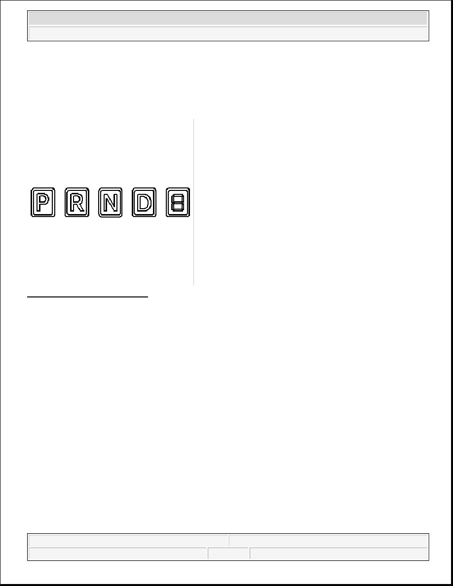
Fig. 21: Gear Selector Indicator 
Courtesy of CHRYSLER LLC 

An electronic automatic transmission gear selector indicator is standard factory-installed equipment on this 
vehicle. However, on vehicles not equipped with an optional automatic transmission, this indicator is 
electronically disabled. The gear selector indicator information is displayed in the upper portion of the odometer 
Vacuum Fluorescent Display (VFD) unit. This VFD unit is soldered onto the cluster electronic circuit board, 
and is visible through a window with a smoked clear lens located on the lower edge of the tachometer dial face 
of the cluster overlay. The dark lens over the VFD unit prevents the indicator from being clearly visible when it 
is not illuminated. 

The gear selector indicator displays the following characters from left to right: P , R , N , D and a fifth, 
reconfigurable character. The reconfigurable character can be any number 1 through 6 . Each character appears 
in a blue-green color and at the same lighting level as the odometer information. Respectively, these characters 
represent the PARK, REVERSE, NEUTRAL, DRIVE and each of the forward drive gear positions of the 
transmission gear selector lever on the floor panel transmission tunnel. The indicator also illuminates a box 
around the character that represents the currently selected lever position. 

During daylight hours (exterior lamps are OFF) the VFD unit is illuminated at full brightness for clear visibility. 
At night (exterior lamps are ON), the VFD unit lighting level is adjusted with the other cluster general 
illumination lamps using the panel lamps dimmer function of the interior lighting control sleeve on the left 
multi-function switch control stalk. However, a PARADE mode position of the control sleeve allows the VFD 
unit to be illuminated at full brightness if the exterior lamps are turned ON during daylight hours. 

The gear selector indicator is serviced as a unit with the VFD unit in the instrument cluster. 


2007 Dodge Nitro R/T 

2007 ACCESSORIES AND EQUIPMENT Instrument Cluster - Service Information - Nitro


OPERATION 

GEAR SELECTOR INDICATOR 

The electronic gear selector indicator gives an indication to the vehicle operator of the transmission gear that 
has been selected with the automatic transmission gear selector lever. This indicator is controlled by the 
instrument cluster circuit board based upon cluster programming and electronic messages received from the 
Powertrain Control Module (PCM) over the Controller Area Network (CAN) data bus. 

The gear selector indicator information is displayed by the odometer Vacuum Fluorescent Display (VFD) unit 
soldered onto the instrument cluster electronic circuit board, and the VFD will not display the gear selector 
indicator information after the ignition switch is turned to the OFF position. Each time the cluster is 
disconnected from battery current for more than about five minutes, it must configure itself for the automatic 
transmission type that is in the vehicle once it is reconnected to battery current. The instrument cluster circuitry 
operates the gear selector indicator to provide the following features: 

Selected Gear Message - Each time the cluster receives an electronic selected gear message from the 
PCM, a box will be illuminated around the appropriate character in the gear selector indicator. The box 
will remain illuminated until the cluster receives a different selected gear message, or until the ignition 
switch is turned to the OFF position, whichever occurs first.  

Communication Error - If the cluster fails to receive a selected gear message from the PCM within 
three seconds, the instrument cluster circuitry will display all gear selector positions boxed (selected) until
a valid selected gear message is received or until the ignition switch is turned to the OFF position, 
whichever occurs first.  

Actuator Test - Each time the cluster is put through the actuator test, the odometer VFD unit will display 
all of its characters at once to confirm the functionality of the VFD unit and the cluster control circuitry.  

The PCM continually monitors a hard wired multiplex input from the Transmission Range Sensor (TRS), then 
sends the proper message to the Electro Mechanical Instrument Cluster (EMIC) (also known as the Cab 
Compartment Node/CCN). 

For proper diagnosis of the TRS, the PCM, the EMIC, the CAN data bus or the electronic communication 
related to gear selector indicator operation a diagnostic scan tool is required. Refer to the appropriate diagnostic 
information. 

HIGH BEAM INDICATOR 

DESCRIPTION 

HIGH BEAM INDICATOR 


2007 Dodge Nitro R/T 

2007 ACCESSORIES AND EQUIPMENT Instrument Cluster - Service Information - Nitro


Fig. 22: High Beam Indicator 
Courtesy of CHRYSLER LLC 

A high beam indicator is standard equipment on all instrument clusters. This indicator is located near the base 
of the speedometer needle hub on the cluster overlay, just left of center. 

The high beam indicator consists of a stencil-like cutout of the International Control and Display Symbol icon 
for High Beam in the opaque layer of the instrument cluster overlay. The dark outer layer of the overlay 
prevents the indicator from being clearly visible when it is not illuminated. A blue Light Emitting Diode (LED) 
behind the cutout in the opaque layer of the overlay causes the indicator to appear in blue through the 
translucent outer layer of the overlay when it is illuminated from behind by the LED, which is soldered onto the 
instrument cluster electronic circuit board. 

The high beam indicator is serviced as a unit with the instrument cluster. 

OPERATION 

HIGH BEAM INDICATOR 

The high beam indicator gives an indication to the vehicle operator whenever the headlamp high beams are 
illuminated. This indicator is controlled by a transistor on the instrument cluster circuit board based upon cluster 
programming and electronic messages received by the cluster from the Totally Integrated Power Module 
(TIPM) over the Controller Area Network (CAN) data bus. 

The high beam indicator Light Emitting Diode (LED) is completely controlled by the instrument cluster logic 
circuit, and that logic will allow this indicator to operate whenever the instrument cluster receives a battery 
current input on the fused B(+) circuit. Therefore, the LED can be illuminated regardless of the ignition switch 
position. The LED only illuminates when it is provided a path to ground by the instrument cluster transistor. 
The instrument cluster will turn ON the high beam indicator for the following reasons: 

High Beam Indicator Lamp-On Message - Each time the cluster receives an electronic high beam 
indicator lamp-ON
 message from the TIPM indicating the high beam lamps are turned ON, the high 
beam indicator will be illuminated. The indicator remains illuminated until the cluster receives a lamp-
OFF message from the TIPM, or until the exterior lamp load shedding (battery saver) timed interval 
expires, whichever occurs first.  

Actuator Test - Each time the cluster is put through the actuator test, the high beam indicator will be 


2007 Dodge Nitro R/T 

2007 ACCESSORIES AND EQUIPMENT Instrument Cluster - Service Information - Nitro


turned ON, then OFF again during the bulb check portion of the test to confirm the functionality of the 
LED and the cluster control circuitry.  

The TIPM continually monitors electronic exterior lighting request messages from the Electro Mechanical 
Instrument Cluster (EMIC) (also known as the Cab Compartment Node/CCN) to determine the appropriate 
outputs to the headlamps. The TIPM activates or deactivates the headlamp high beams then sends the proper 
lamp-ON or lamp-OFF message back to the EMIC. 

For proper diagnosis of the headlamp system, the TIPM, the EMIC, the CAN data bus or the electronic 
communication related to high beam indicator operation a diagnostic scan tool is required. Refer to the 
appropriate diagnostic information. 

INSTRUMENT PANEL SWITCH POD 

DESCRIPTION 

INSTRUMENT PANEL SWITCH POD 

Fig. 23: Identifying Occupant Classification System Switches & Indicators 
Courtesy of CHRYSLER LLC 

The instrument panel switch pod (1) is located just below the heater and air conditioner controls in the center 
stack area of the instrument panel. This switch is available in multiple configurations, which varies from two 
single push button switches to as many as five push button switches and an indicator lamp, depending upon the 
optional equipment in the vehicle. The pod may include the following switches or indicators: 

Alternating Current (AC) Power Inverter Outlet Switch (5)  

Driver and Passenger Side Heated Seat Switches (2)  

Hazard Warning Switch (3)  

Headlamp Leveling Switch (Not Shown)  

Park Assist Switch (Not Shown)  

Passenger Airbag On/Off Indicator (4)  

Electronic Stability Program (ESP) Switch (6)  

The switch housing and the push buttons are constructed of molded plastic. Each push button has a smooth 
finish and is clearly identified with the appropriate text and International Control and Display Symbol icons. 
Several of the push buttons feature Light Emitting Diode (LED) units to give the vehicle operator an indication 
when the function of that switch is currently active. Only the hazard warning switch push button latches, while 


2007 Dodge Nitro R/T 

2007 ACCESSORIES AND EQUIPMENT Instrument Cluster - Service Information - Nitro


Content   ..  805  806  807  808   ..