Dodge Nitro. Manual - part 801


  Index      Dodge     Dodge Nitro - service repair manual 2007 year


Search            


Content   ..  799  800  801  802   ..


Dodge Nitro. Manual - part 801


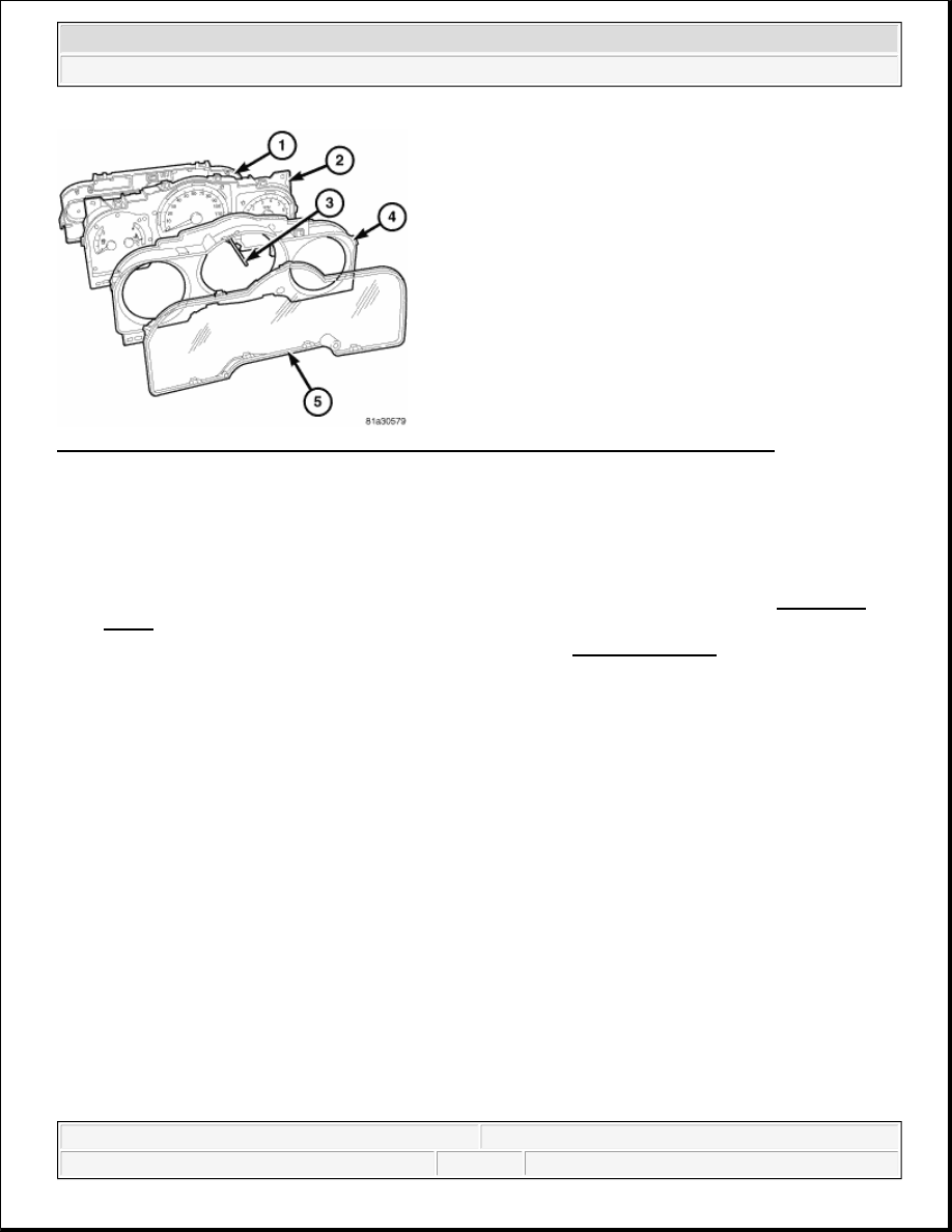
Fig. 8: Identifying Plastic Rear Cover, Cluster Housing, Plastic Cluster Lens & Mask Unit 
Courtesy of CHRYSLER LLC 

1. Position the cluster hood and mask unit (3) over the face of the cluster housing (2). Be certain that the 

odometer/trip odometer switch push button is inserted through the clearance hole in the mask.  

2. Working around the perimeter of the cluster, press the hood and mask over the face of the cluster housing 

until each of the eight integral latch features is fully engaged in the receptacles of the housing.  

3. Reinstall the cluster lens (5) onto the face of the cluster hood and mask unit. Refer to step CLUSTER 

LENS.  

4. Reinstall the instrument cluster onto the instrument panel. See INSTALLATION.  

5. Reconnect the battery negative cable.  

INSTALLATION 

INSTRUMENT CLUSTER 

WARNING:

To avoid serious or fatal injury on vehicles equipped with airbags, disable 
the Supplemental Restraint System (SRS) before attempting any steering 
wheel, steering column, airbag, Occupant Classification System (OCS), 
seat belt tensioner, impact sensor, or instrument panel component 
diagnosis or service. Disconnect and isolate the battery negative (ground) 
cable, then wait two minutes for the system capacitor to discharge before 
performing further diagnosis or service. This is the only sure way to 
disable the SRS. Failure to take the proper precautions could result in 
accidental airbag deployment.


2007 Dodge Nitro R/T 

2007 ACCESSORIES AND EQUIPMENT Instrument Cluster - Service Information - Nitro


Fig. 9: Removing/Installing Screws That Secure Instrument Cluster To Instrument Panel Base Trim 
Courtesy of CHRYSLER LLC 

1. Position the instrument cluster (1) close enough to the instrument panel to reconnect the instrument panel 

wire harness connectors to the connector receptacles on the back of the cluster housing.  

2. Position the instrument cluster mounting tabs to the mounting holes in the instrument panel base trim (2). 

3. Install and tighten the four screws (3) that secure the mounting tabs of the instrument cluster. Tighten the 

screws to 2 N.m (17 in. lbs.).  

4. Reinstall the cluster bezel onto the instrument panel. Refer to INSTALLATION .  

5. Reconnect the battery negative cable.  

SPECIFICATIONS 

INSTRUMENT CLUSTER 

TORQUE SPECIFICATIONS 

NOTE:

Certain indicators in this instrument cluster are automatically configured. This 
feature allows those indicators to be activated or deactivated for compatibility 
with certain optional equipment. If a problem is noted that involves improper 
illumination of an indicator, disconnect and isolate the battery negative cable. 
After about five minutes, reconnect the battery negative cable and turn the 
ignition switch to the ON position. The instrument cluster should automatically 
relearn the equipment in the vehicle and properly configure the configurable 
indicators accordingly.

DESCRIPTION 

N-m 

Ft. Lbs. 

In. Lbs. 

Instrument Cluster 

Mounting Screws

2

-

17

Instrument Panel Switch 

Pod Mounting Screws

2

-

17


2007 Dodge Nitro R/T 

2007 ACCESSORIES AND EQUIPMENT Instrument Cluster - Service Information - Nitro


ABS INDICATOR 

DESCRIPTION 

ABS INDICATOR 

Fig. 10: ABS Indicator 
Courtesy of CHRYSLER LLC 

An Antilock Brake System (ABS) indicator is standard equipment on all instrument clusters. This indicator is 
located near the bottom of the speedometer dial face of the cluster overlay, just left of center. Illumination of 
this indicator may also be accompanied by the display of certain textual messages in the cluster odometer 
display. 

The ABS indicator consists of a stencil-like cutout of the International Control and Display Symbol icon for 
Failure of Anti-lock Braking System in the opaque layer of the instrument cluster overlay. The dark outer 
layer of the overlay prevents the indicator from being clearly visible when it is not illuminated. An amber Light 
Emitting Diode (LED) behind the cutout in the opaque layer of the overlay causes the indicator to appear in 
amber through the translucent outer layer of the overlay when it is illuminated from behind by the LED, which 
is soldered onto the instrument cluster electronic circuit board. 

The ABS indicator is serviced as a unit with the instrument cluster. 

OPERATION 

ABS INDICATOR 

The ABS indicator gives an indication to the vehicle operator when the ABS system, or a circuit or component 
of the system is ineffective. This indicator is controlled by a transistor on the instrument cluster circuit board 
based upon cluster programming and electronic messages received by the cluster from the Controller Antilock 
Brake (CAB) over the Controller Area Network (CAN) data bus. 

The ABS indicator Light Emitting Diode (LED) is completely controlled by the instrument cluster logic circuit, 
and that logic will only allow this indicator to operate when the instrument cluster receives a battery current 
input on the fused ignition switch output (run-start) circuit. Therefore, the LED will always be OFF when the 


2007 Dodge Nitro R/T 

2007 ACCESSORIES AND EQUIPMENT Instrument Cluster - Service Information - Nitro


ignition switch is in any position except ON or START. The LED only illuminates when it is provided a path to 
ground by the instrument cluster transistor. The instrument cluster will turn ON the ABS indicator for the 
following reasons: 

Bulb Test - Each time the ignition switch is turned to the ON position the ABS indicator is illuminated 
for about three seconds as a bulb test. The entire bulb test is a function of the CAB.  

ABS Indicator Lamp-On Message - Each time the cluster receives an electronic ABS indicator lamp-
ON
 message from the CAB, the ABS indicator will be illuminated. The indicator remains illuminated 
until the cluster receives a lamp-OFF message from the CAB, or until the ignition switch is turned to the 
OFF position, whichever occurs first.  

Communication Error - If the cluster receives no lamp-ON or lamp-OFF messages from the CAB for 
five consecutive message cycles, the ABS indicator is illuminated. The indicator remains illuminated 
until the cluster receives a valid message from the CAB, or until the ignition switch is turned to the OFF 
position, whichever occurs first.  

Actuator Test - Each time the instrument cluster is put through the actuator test and the Totally 
Integrated Power Module (TIPM) is configured for the ABS option, the ABS indicator will be turned ON, 
then OFF again during the bulb check portion of the test to confirm the functionality of the LED and the 
cluster control circuitry.  

ABS Diagnostic Test - The ABS indicator is blinked ON and OFF by lamp-ON and lamp-OFF messages 
from the CAB during the performance of the ABS diagnostic tests.  

The CAB continually monitors the ABS circuits and sensors to decide whether the system is in good operating 
condition. The CAB then sends the proper lamp-ON or lamp-OFF message to the Electro Mechanical 
Instrument Cluster (EMIC) (also known as the Cab Compartment Node/CCN). If the CAB sends a lamp-ON 
message after the bulb test, it indicates that the CAB has detected a system malfunction or that the ABS system 
has become ineffective. The CAB will store a Diagnostic Trouble Code (DTC) for any malfunction it detects. 
Each time the ABS indicator fails to light due to an open or short in the cluster ABS indicator circuit, the cluster 
sends a message notifying the CAB of the condition, then the instrument cluster and the CAB will each store a 
DTC and the cluster will flash the brake indicator ON and OFF as a backup to notify the vehicle operator. 

For proper diagnosis of the antilock brake system, the CAB, the EMIC, the CAN data bus or the electronic 
communication related to ABS indicator operation a diagnostic scan tool is required. Refer to the appropriate 
diagnostic information. 

AIRBAG INDICATOR 

DESCRIPTION 

AIRBAG INDICATOR 


2007 Dodge Nitro R/T 

2007 ACCESSORIES AND EQUIPMENT Instrument Cluster - Service Information - Nitro


Content   ..  799  800  801  802   ..