Dodge Nitro. Manual - part 800


  Index      Dodge     Dodge Nitro - service repair manual 2007 year


Search            


Content   ..  798  799  800  801   ..


Dodge Nitro. Manual - part 800


units, and perform a bulb check of each operational LED indicator. The VFD segments and LED 
indicators remain illuminated as each gauge needle is swept to several calibration points and back. If a 
VFD segment or an LED indicator fails to illuminate, or if a gauge needle fails to sweep through the 
calibration points and back during this test, the instrument cluster must be replaced.  

6. The actuator test is now completed. The instrument cluster will automatically exit the self-diagnostic 

mode and return to normal operation at the completion of the test. The actuator test will be aborted if the 
ignition switch is turned to the OFF position, or if an electronic vehicle speed message indicating that the 
vehicle is moving is received over the CAN data bus during the test.  

7. Go back to step 1 to repeat the test, if necessary.  

REMOVAL 

INSTRUMENT CLUSTER 

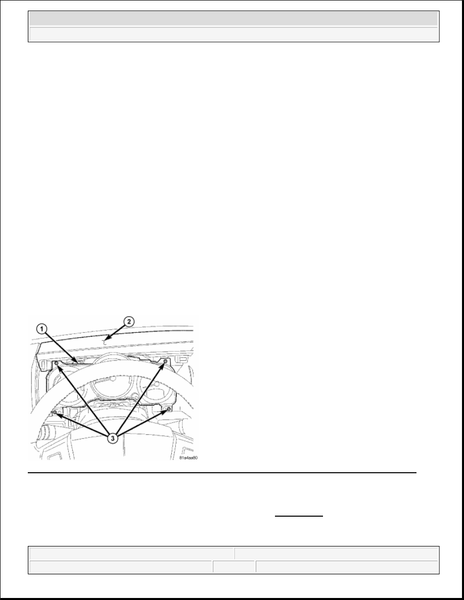
Fig. 4: Removing/Installing Screws That Secure Instrument Cluster To Instrument Panel Base Trim 
Courtesy of CHRYSLER LLC 

1. Disconnect and isolate the battery negative cable.  

2. Remove the cluster bezel from the instrument panel. Refer to REMOVAL .  

3. Remove the four screws (3) that secure the instrument cluster (1) to the instrument panel base trim (2).  

4. Pull the top of the instrument cluster rearward far enough to access and disconnect the instrument panel 

WARNING:

To avoid serious or fatal injury on vehicles equipped with airbags, disable 
the Supplemental Restraint System (SRS) before attempting any steering 
wheel, steering column, airbag, Occupant Classification System (OCS), 
seat belt tensioner, impact sensor, or instrument panel component 
diagnosis or service. Disconnect and isolate the battery negative (ground) 
cable, then wait two minutes for the system capacitor to discharge before 
performing further diagnosis or service. This is the only sure way to 
disable the SRS. Failure to take the proper precautions could result in 
accidental airbag deployment.


2007 Dodge Nitro R/T 

2007 ACCESSORIES AND EQUIPMENT Instrument Cluster - Service Information - Nitro


wire harness connectors from the connector receptacles on the back of the cluster housing. 

5. Remove the instrument cluster from the instrument panel.  

DISASSEMBLY 

INSTRUMENT CLUSTER 

CLUSTER LENS 

Fig. 5: Identifying Plastic Rear Cover, Cluster Housing, Plastic Cluster Lens & Mask Unit 
Courtesy of CHRYSLER LLC 

1. Disconnect and isolate the battery negative cable.  

2. Remove the instrument cluster from the instrument panel. See REMOVAL.  

3. Working around the perimeter of the cluster, disengage each of the nine integral latch features that secure 

the cluster lens (5) to the cluster hood and mask unit (3) and to the cluster housing (2).  

WARNING:

To avoid serious or fatal injury on vehicles equipped with airbags, disable 
the Supplemental Restraint System (SRS) before attempting any steering 
wheel, steering column, airbag, Occupant Classification System (OCS), 
seat belt tensioner, impact sensor, or instrument panel component 
diagnosis or service. Disconnect and isolate the battery negative (ground) 
cable, then wait two minutes for the system capacitor to discharge before 
performing further diagnosis or service. This is the only sure way to 
disable the SRS. Failure to take the proper precautions could result in 
accidental airbag deployment.

NOTE:

Some of the components for the instrument cluster used in this vehicle are 
serviced individually. The serviced components include the cluster lens and the 
cluster hood and mask unit. Following are the procedures for disassembling 
these components from the instrument cluster.


2007 Dodge Nitro R/T 

2007 ACCESSORIES AND EQUIPMENT Instrument Cluster - Service Information - Nitro


4. Remove the lens from the face of the cluster hood and mask unit.  

CLUSTER HOOD AND MASK 

Fig. 6: Identifying Plastic Rear Cover, Cluster Housing, Plastic Cluster Lens & Mask Unit 
Courtesy of CHRYSLER LLC 

1. Disconnect and isolate the battery negative cable.  

2. Remove the instrument cluster from the instrument panel. See REMOVAL.  

3. Remove the cluster lens (5) from the face of the cluster hood and mask unit (3). Refer to step CLUSTER 

LENS.  

4. Working around the perimeter of the cluster, disengage each of the eight integral latch features that secure 

the cluster hood and mask unit to the cluster housing (2).  

5. Remove the hood and mask unit from the face of the instrument cluster.  

ASSEMBLY 

INSTRUMENT CLUSTER 

WARNING:

To avoid serious or fatal injury on vehicles equipped with airbags, disable 
the Supplemental Restraint System (SRS) before attempting any steering 
wheel, steering column, airbag, Occupant Classification System (OCS), 
seat belt tensioner, impact sensor, or instrument panel component 
diagnosis or service. Disconnect and isolate the battery negative (ground) 
cable, then wait two minutes for the system capacitor to discharge before 
performing further diagnosis or service. This is the only sure way to 
disable the SRS. Failure to take the proper precautions could result in 
accidental airbag deployment.

NOTE:

Some of the components for the instrument cluster used in this vehicle are 
serviced individually. The serviced components include the cluster lens and the 


2007 Dodge Nitro R/T 

2007 ACCESSORIES AND EQUIPMENT Instrument Cluster - Service Information - Nitro


CLUSTER LENS 

Fig. 7: Identifying Plastic Rear Cover, Cluster Housing, Plastic Cluster Lens & Mask Unit 
Courtesy of CHRYSLER LLC 

1. Position the cluster lens (5) over the face of the cluster hood and mask unit (3). Be certain that the rubber 

grommet (4) for the odometer/trip odometer switch push button is installed in the clearance hole in the 
lens, and that the push button is engaged through the grommet.  

2. Working around the perimeter of the cluster, press the lens over the face of the hood and mask until each 

of the nine integral latch features is fully engaged in the receptacles of the hood and mask or the cluster 
housing (2).  

3. Reinstall the instrument cluster onto the instrument panel. See INSTALLATION.  

4. Reconnect the battery negative cable.  

CLUSTER HOOD AND MASK 

cluster hood and mask unit. Following are the procedures for assembling these 
components onto the instrument cluster.


2007 Dodge Nitro R/T 

2007 ACCESSORIES AND EQUIPMENT Instrument Cluster - Service Information - Nitro


Content   ..  798  799  800  801   ..