Dodge Nitro. Manual - part 647


  Index      Dodge     Dodge Nitro - service repair manual 2007 year


Search            


Content   ..  645  646  647  648   ..


Dodge Nitro. Manual - part 647


integral screw-drive transmission. The ball on the end of the pushrod is snapped into a socket on the back of the 
reflector within the front lamp unit housing, which will cause the reflector to move as the pushrod is extended 
or retracted, changing the angle at which the light is projected from the headlamp low beam bulb filaments. 

The hard wired circuits for the headlamp leveling motors may be diagnosed using conventional diagnostic tools 
and procedures. Refer to the appropriate wiring information. However, conventional diagnostic methods will 
not prove conclusive in the diagnosis of the active electronic elements within the headlamp leveling motors or 
the electronic controls and communication between other modules and devices that provide some features of the 
headlamp leveling system. The most reliable, efficient, and accurate means to diagnose the headlamp leveling 
motor or the electronic controls and communication related to headlamp leveling system operation requires the 
use of a diagnostic scan tool. Refer to the appropriate diagnostic information. 

SWITCH-HEADLAMP LEVELING 

DESCRIPTION 

HEADLAMP LEVELING SWITCH 

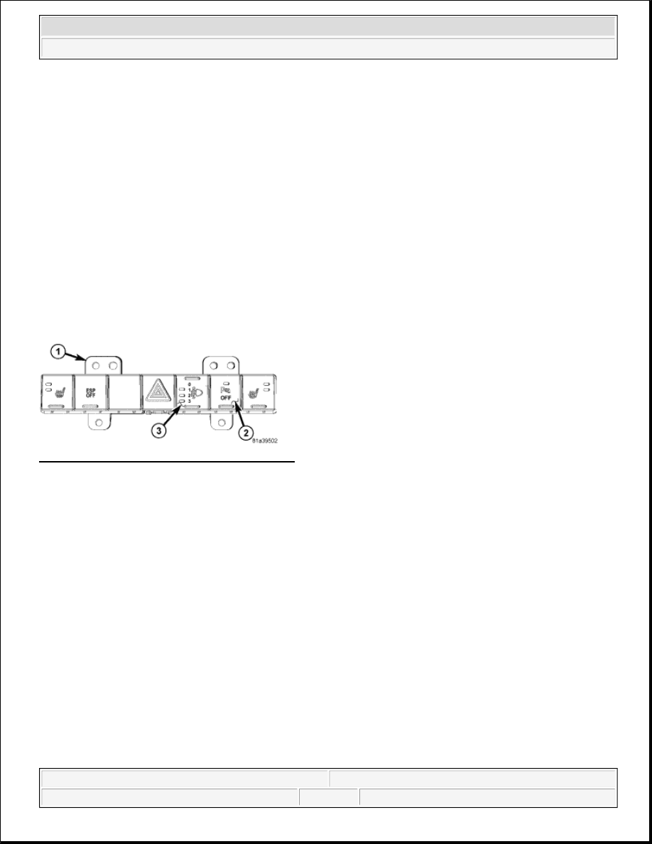
Fig. 30: Identifying Headlamp Leveling Switch 
Courtesy of CHRYSLER LLC 

The headlamp leveling switch (3) is used only on vehicles manufactured for certain markets where the 
headlamp leveling system is required. The headlamp leveling switch is integral to the switch pod (1) on the 
instrument panel. A stencil-like International Control and Display Symbol icon for Headlamp Levelling 
Control
 identifies the headlamp leveling switch button. The switch push button is also marked with the 
numbers 0 , 1 , 2 , and 3 , which indicates each of the four headlamp leveling positions. Each higher number 
represents a lower aiming position of the headlamp beam relative to the road surface. 

The headlamp leveling switch button has panel lamps dimmer controlled illumination for night visibility. The 
switch button also features a jewel like Light Emitting Diode (LED) indicator adjacent to the numbers 1 , 2 , 
and 3 . The appropriate LED is illuminated when that headlamp position is currently selected. The momentary 
switch push button is operated by depressing, then releasing the top or bottom of the button in a rocker manner 
to enable the selection of a sequentially higher or lower position with each button press. 

All of the circuitry and components of the headlamp leveling switch are contained within a molded black plastic 
instrument panel switch pod housing. A single connector receptacle is integral to the back of the switch pod 
housing. The switch is connected to the vehicle electrical system through a dedicated take out and connector of 
the instrument panel wire harness. 

The headlamp leveling switch cannot be adjusted or repaired and, if ineffective or damaged, the entire 


2007 Dodge Nitro R/T 

2007 ACCESSORIES AND EQUIPMENT Lamps/Lighting - Exterior - Service Information - Nitro


instrument panel switch pod unit must be replaced. Refer to REMOVAL .

OPERATION 

HEADLAMP LEVELING SWITCH 

The status of the headlamp leveling switch is continually monitored by the circuitry within the instrument panel 
switch pod. The switch pod receives battery voltage at all times on a fused battery feed circuit, and a path to 
ground at all times through the instrument panel wire harness. The only other inputs to and outputs from the 
switch pod consist of electronic communication with the Electro Mechanical Instrument Cluster (EMIC) (also 
known as the Cab Compartment Node/CCN) over the single wire Local Interface Network (LIN) data bus. 

Whenever the headlamp leveling switch push button is depressed the switch pod circuitry sends an electronic 
select status up or select status down message input to the EMIC over the LIN data bus. The EMIC then sends 
the appropriate electronic select request up or select request down message to the TIPM over the CAN data 
bus. 

The TIPM responds to these messages by providing a voltage output to the headlamp leveling motors through 
high side drivers on the headlamp leveling motor right and left signal circuits to move the headlamp reflectors 
to the selected position based upon the voltage input received from the TIPM. The TIPM also sends the 
appropriate electronic messages back to the EMIC and the EMIC relays the messages back to the switch pod to 
control the illumination of the 1 , 2 , or 3 Light Emitting Diode (LED) selected position indicator in the leveling 
switch button. The EMIC and TIPM logic will only allow the headlamp leveling system to operate while the 
ignition switch is in the ON position and the exterior lighting is turned ON. 

The hard wired circuits for the instrument panel switch pod may be diagnosed using conventional diagnostic 
tools and procedures. Refer to the appropriate wiring information. However, conventional diagnostic methods 
will not prove conclusive in the diagnosis of the headlamp leveling switch or the electronic controls and 
communication between other modules and devices that provide some features of the headlamp leveling system. 
The most reliable, efficient, and accurate means to diagnose the headlamp leveling switch or the electronic 
controls and communication related to headlamp leveling system operation requires the use of a diagnostic scan 
tool. Refer to the appropriate diagnostic information. 

LEFT MULTI-FUNCTION SWITCH 

DESCRIPTION 

LEFT MULTI- FUNCTION SWITCH 


2007 Dodge Nitro R/T 

2007 ACCESSORIES AND EQUIPMENT Lamps/Lighting - Exterior - Service Information - Nitro


Fig. 31: Identifying Control Knob, Control Stalk & Control Sleeve 
Courtesy of CHRYSLER LLC 

The left (lighting) multi-function switch is located on the left side of the steering column, just below the 
steering wheel. This switch is the primary control for the interior and exterior lighting systems. The only visible 
components of the switch are the control stalk (2), control knob (1) and control sleeve (3) that extend through 
the steering column shrouds on the left side of the column. The remainder of the switch including its mounting 
provisions, its electrical connection, and the turn signal cancel actuator are concealed beneath the shrouds. 

Fig. 32: Steering Control Module Components 
Courtesy of CHRYSLER LLC 

The switch housing (2) and controls (1) are constructed of molded black plastic. Each of the switch controls has 
white International Control and Display Symbol graphics applied to it, which clearly identify its many 
functions. A single screw (7) through a mounting tab integral to the back of the switch housing, and a slide tab 


2007 Dodge Nitro R/T 

2007 ACCESSORIES AND EQUIPMENT Lamps/Lighting - Exterior - Service Information - Nitro


integral to the bottom of the switch housing secure the switch to the mounting bracket integral to the 
clockspring (3). 

The Steering Control Module (SCM) is internal to the switch housing. The switch outputs are internally 
connected directly to the SCM. A single connector receptacle containing seven terminal pins is integral to the 
inboard end of the switch housing and connects the right multi-function switch (6) through a jumper wire 
harness (5) directly to the SCM. An integral connector receptacle on the back of the switch housing connects 
the SCM to the vehicle electrical system through a dedicated take out and connector of the instrument panel 
wire harness. 

The left multi-function switch provides the vehicle operator with a control interface for the following exterior 
lighting system functions: 

Front Fog Lamps - For vehicles so equipped, the left multi-function switch control knob provides detent 
switching for the optional front fog lamps.  

Headlamps - The left multi-function switch control knob provides detent switching for the headlamps.  

Headlamp Beam Selection - The left multi-function switch control stalk provides detent switching for 
selection of the headlamp high or low beams.  

Headlamp Optical Horn - The left multi-function switch control stalk includes momentary switching of 
the headlamp high beam circuits to provide an optical horn feature (sometimes referred to as flash-to-
pass), which allows the vehicle operator to momentarily flash the headlamp high beams as an optical 
signalling device.  

Park Lamps - The left multi-function switch control knob provides detent switching for the park lamps.  

Rear Fog Lamps - For vehicles so equipped, the left multi-function switch control knob provides detent 
switching for the optional rear fog lamps. Rear fog lamps are optional only for vehicles manufactured for 
certain markets, where they are required.  

Turn Signal Control - The left multi-function switch control stalk provides both momentary non-detent 
switching and detent switching with automatic cancellation for both the left and right turn signal lamps.  

The left multi-function switch also provides the vehicle operator with a control interface for the following 
interior lighting functions: 

Interior Lamps Defeat - The left multi-function switch control ring provides detent switching to 
DEFEAT the illumination of all interior courtesy lamps when a door, the rear flip-up glass, or the liftgate 
are opened.  

Interior Lamps On - The left multi-function switch control ring provides detent switching to 
simultaneously illuminate all interior courtesy lamps.  

Panel Lamps Dimming - The left multi-function switch control ring provides simultaneous adjustable 
control of the illumination intensity of all instrument panel lighting at one of five available illumination 
intensity levels.  

Parade Mode - The left multi-function switch control ring provides detent switching for a PARADE 
mode that maximizes the illumination intensity of all instrument panel lighting for visibility when driving 
in daylight with the exterior lamps turned ON.  

The left multi-function switch cannot be adjusted or repaired. If any function of the switch is ineffective, or if 


2007 Dodge Nitro R/T 

2007 ACCESSORIES AND EQUIPMENT Lamps/Lighting - Exterior - Service Information - Nitro


Content   ..  645  646  647  648   ..