Dodge Nitro. Manual - part 223


  Index      Dodge     Dodge Nitro - service repair manual 2007 year


Search            


Content   ..  221  222  223  224   ..


Dodge Nitro. Manual - part 223


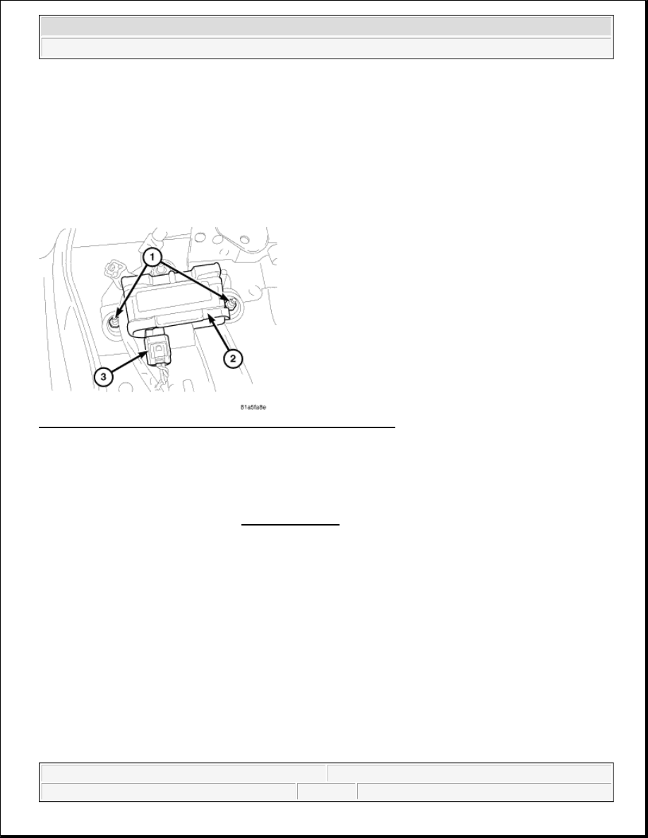
2. Disconnect electrical connector (3) from the dynamics sensor (2).  

3. Remove the two nuts (1) securing the sensor to the floor.  

4. Remove the sensor (2).  

INSTALLATION 

SENSOR-DYNAMICS 

Fig. 7: Identifying Nuts, Dynamics Sensor & Electrical Connector 
Courtesy of CHRYSLER LLC 

1. Install the dynamics sensor (2) to the vehicle.  

2. Install the electrical connector (3) making sure that the connector is fully seated into the sensor (2)  

3. Install the two retaining nuts (1) and tighten to 9 N.m (80 in. lbs.).  

4. Install the floor console. Refer to INSTALLATION .  

SENSOR-STEERING ANGLE 

DESCRIPTION 

SENSOR-STEERING ANGLE 

Under transient cornering conditions the lateral acceleration sensor does not measure the true sway force on the 
car. In order to compensate for this the system uses the driver's steering command (Steering angle sensor) and 
vehicle speed to estimate the true sway force. This signal is matched with the lateral acceleration sensor signal 
to ensure a significantly-reduced transient sway of the vehicle body. 

REMOVAL 

NOTE:

Steering angle sensor is part of the airbag clockspring and is not serviced 
separately from the clockspring.


2007 Dodge Nitro R/T 

2007 BRAKES ABS Service Information - Nitro


SENSOR-STEERING ANGLE 

1. For removal of the steering angle sensor. Refer to REMOVAL .  

INSTALLATION 

SENSOR-STEERING ANGLE 

1. For installation of the steering angle sensor. Refer to INSTALLATION .  

ESP SWITCH 

DESCRIPTION 

SWITCH - ESP 

Fig. 8: Identifying Instrument Panel Switches 
Courtesy of CHRYSLER LLC 

The ESP switch (5) is located in the center stack (1) of the instrument panel. If the switch is damaged or 
inoperative the complete accessory switch bank assembly must be replaced. 

REMOVAL 

SWITCH - ESP 

NOTE:

Steering angle sensor is part of the airbag clockspring and is not serviced 
separately from the clockspring.

NOTE:

Steering angle sensor is part of the airbag clockspring and is not serviced 
separately from the clockspring.

WARNING:

On vehicles equipped with airbags, disable the airbag system before 


2007 Dodge Nitro R/T 

2007 BRAKES ABS Service Information - Nitro


Fig. 9: Identifying Center Bezel, Screws & Accessory Switch Bank 
Courtesy of CHRYSLER LLC 

1. Disconnect and isolate the battery negative cable.  

2. Remove the center bezel from the instrument panel, refer to REMOVAL .  

3. Remove the four screws (2) that secure the accessory switch bank (3) to the back of the center bezel (1) 

and remove the switch bank.  

INSTALLATION 

SWITCH - ESP 

attempting any steering wheel, steering column, or instrument panel 
component diagnosis or service. Disconnect and isolate the negative 
battery (ground) cable, then wait two minutes for the airbag system 
capacitor to discharge before performing further diagnosis or service. 
This is the only sure way to disable the airbag system. Failure to take the 
proper precautions could result in accidental airbag deployment and 
possible personal injury or death.

NOTE:

The ESP switch is integral to the accessory switch bank and cannot be serviced 
separately. The complete accessory switch bank assembly must be replaced.


2007 Dodge Nitro R/T 

2007 BRAKES ABS Service Information - Nitro


Fig. 10: Identifying Center Bezel, Screws & Accessory Switch Bank 
Courtesy of CHRYSLER LLC 

1. Position the accessory switch bank (3) onto the back of the instrument panel center bezel (1).  

2. Install the four screws (2) that secure the accessory switch bank to the center bezel. Tighten the screws to 

2 N.m (17 in. lbs.).  

3. Install the center bezel onto the instrument panel, refer to INSTALLATION .  

4. Connect the battery negative cable.  

5. Verify ESP system operation.  

HYDRAULIC/MECHANICAL 

HCU (HYDRAULIC CONTROL UNIT) 

DESCRIPTION 

HYDRAULIC CONTROL UNIT 

The HCU consists of a valve body, pump motor, and wire harness. 

OPERATION 

HYDRAULIC CONTROL UNIT 

Accumulators in the valve body store extra fluid released to the system for ABS mode operation. The pump 
provides the fluid volume needed and is operated by a DC type motor. The motor is controlled by the ABM. 

The valves modulate brake pressure during antilock braking and are controlled by the ABM. 

NOTE:

There are different accessory switch banks available based on the option 
content of the vehicle. Ensure the switch pod being installed matches the 
vehicle options.


2007 Dodge Nitro R/T 

2007 BRAKES ABS Service Information - Nitro


Content   ..  221  222  223  224   ..