Dodge Durango (DN). Manual - part 460


  Index      Dodge     Dodge Durango (DN) - service repair manual 2000 year


Search            


Content   ..  458  459  460  461   ..


Dodge Durango (DN). Manual - part 460


(10) Remove the vibration damper bolt and seal

installation tool.

(11) Install vibration damper.

(12) Install water pump and housing assembly

using new gaskets (refer to Group 7, Cooling Sys-
tem). Tighten bolts to 41 N·m (30 ft. lbs.) torque.

(13) Install power steering pump (refer to Group

19, Steering).

(14) Install the serpentine belt (refer to Group 7,

Cooling System).

(15) Install the cooling system fan. Tighten the

bolts to 23 N·m (17 ft. lbs.) torque.

(16) Position the fan shroud and install the bolts.

Tighten the bolts to 11 N·m (95 in. lbs.) torque.

(17) Fill cooling system (refer to Group 7, Cooling

System for the proper procedure).

(18) Connect the negative cable to the battery.

TIMING CHAIN

REMOVAL

(1) Disconnect battery negative cable.
(2) Remove Timing Chain Cover. Refer to Timing

Chain Cover in this section for correct procedure.

(3) Re-install the vibration damper bolt finger

tight. Using a suitable socket and breaker bar, rotate
the crankshaft to align timing marks as shown in
(Fig. 57).

(4) Remove camshaft sprocket attaching bolt and

remove timing chain with crankshaft and camshaft
sprockets.

INSTALLATION

(1) Place both camshaft sprocket and crankshaft

sprocket on the bench with timing marks on exact
imaginary center line through both camshaft and
crankshaft bores.

(2) Place timing chain around both sprockets.
(3) Turn crankshaft and camshaft to line up with

keyway location in crankshaft sprocket and in cam-
shaft sprocket.

(4) Lift sprockets and chain (keep sprockets tight

against the chain in position as described).

(5) Slide both sprockets evenly over their respec-

tive shafts and use a straightedge to check alignment
of timing marks (Fig. 57).

(6) Install the camshaft bolt. Tighten the bolt to 68

N·m (50 ft. lbs.) torque.

(7) Check camshaft end play. The end play should

be 0.051-0.152 mm (0.002-0.006 inch) with a new
thrust plate and up to 0.254 mm (0.010 inch) with a
used thrust plate. If not within these limits install a
new thrust plate.

(8) Install the timing chain cover.

CAMSHAFT

NOTE: The camshaft has an integral oil pump and
distributor drive gear (Fig. 58).

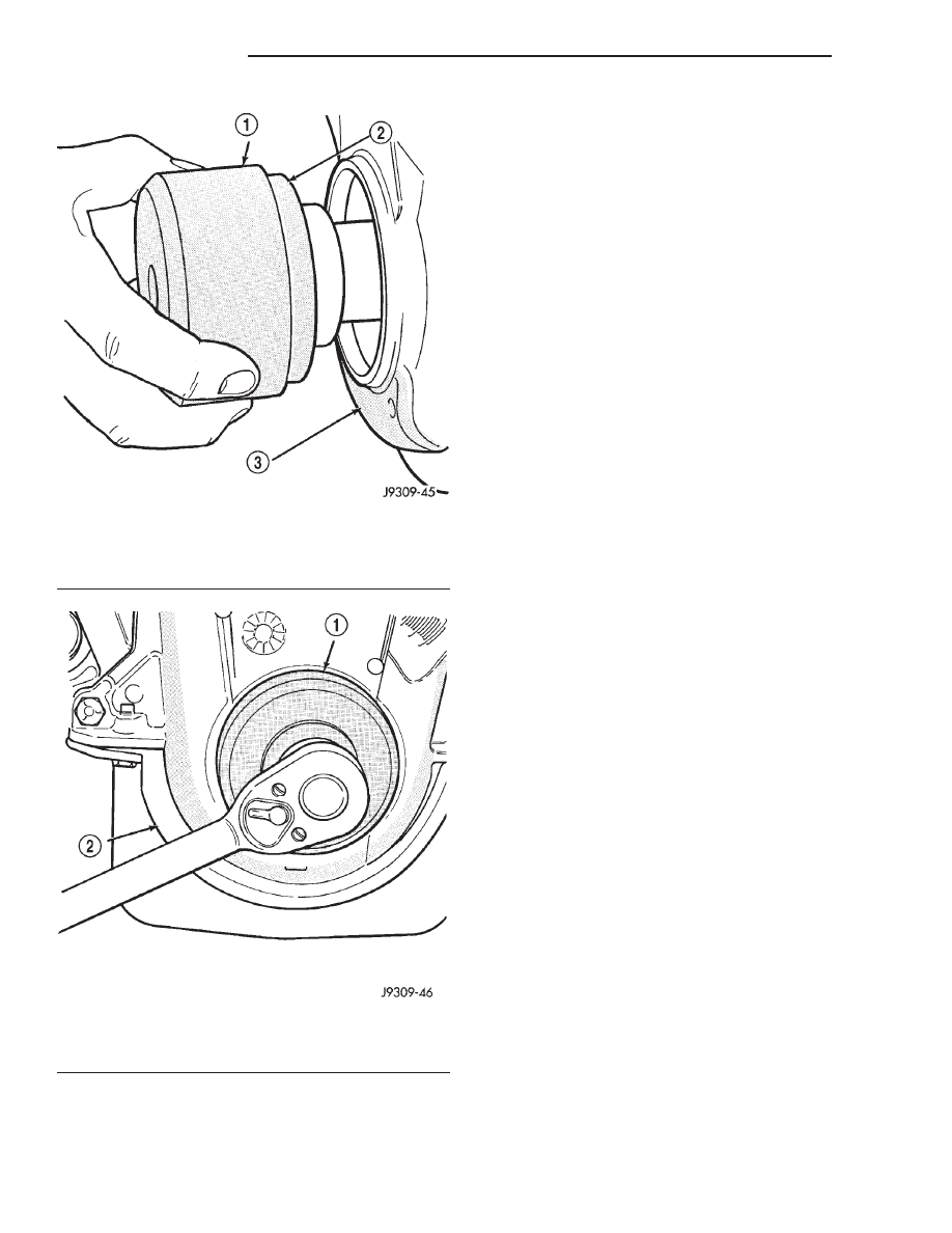
Fig. 55 Position Tool and Seal onto Crankshaft

1 – SPECIAL TOOL 6635
2 – OIL SEAL
3 – TIMING CHAIN COVER

Fig. 56 Installing Oil Seal

1 – SPECIAL TOOL 6635
2 – TIMING CHAIN COVER

9 - 170

5.9L ENGINE

DN

REMOVAL AND INSTALLATION (Continued)

REMOVAL

(1) Remove the radiator. Refer to Group 7, Cooling

for the correct procedures.

(2) Remove the A/C Condenser (if equipped).
(3) Remove the engine cover.
(4) Remove intake manifold. Refer to Intake Man-

ifold in this section for the correct procedure.

(5) Remove cylinder head covers.
(6) Remove timing case cover and timing chain.
(7) Remove rocker arms.
(8) Remove push rods and tappets. Identify each

part so it can be installed in its original location.

(9) Remove distributor and lift out the oil pump

and distributor drive shaft.

(10) Remove camshaft thrust plate, note location of

oil tab (Fig. 59).

(11) Install a long bolt into front of camshaft to aid

in removal of the camshaft. Remove camshaft, being
careful not to damage cam bearings with the cam
lobes.

INSTALLATION

(1) Lubricate camshaft lobes and camshaft bearing

journals and insert the camshaft to within 51 mm (2
inches) of its final position in cylinder block.

(2) Install Camshaft Gear Installer Tool C-3509

with tongue back of distributor drive gear (Fig. 60).

(3) Hold tool in position with a distributor lock-

plate bolt. This tool will restrict camshaft from being
pushed in too far and prevent knocking out the welch
plug in rear of cylinder block. Tool should remain
installed until the camshaft and crankshaft
sprockets and timing chain have been installed.

(4) Install camshaft thrust plate and chain oil tab.

Make sure tang enters lower right hole in
thrust plate. 
Tighten bolts to 24 N·m (210 in. lbs.)

Fig. 57 Alignment of Timing Marks

1 – TIMING MARKS

Fig. 58 Camshaft and Sprocket Assembly

1 – THRUST PLATE
2 – OIL PUMP AND DISTRIBUTOR DRIVE GEAR INTEGRAL

WITH CAMSHAFT

3 – CAMSHAFT SPROCKET

Fig. 59 Timing Chain Oil Tab Installation

1 – THRUST PLATE FRONT SIDE
2 – CHAIN OIL TAB
3 – THRUST PLATE REAR SIDE

Fig. 60 Camshaft Holding Tool C-3509 (Installed

Position)

1 – SPECIAL TOOL C-3509
2 – DRIVE GEAR
3 – DISTRIBUTOR LOCK BOLT

DN

5.9L ENGINE

9 - 171

REMOVAL AND INSTALLATION (Continued)

torque. Top edge of tab should be flat against thrust
plate in order to catch oil for chain lubrication.

(5) Place both camshaft sprocket and crankshaft

sprocket on the bench with timing marks on exact
imaginary center line through both camshaft and
crankshaft bores.

(6) Place timing chain around both sprockets.
(7) Turn crankshaft and camshaft to line up with

keyway location in crankshaft sprocket and in cam-
shaft sprocket.

(8) Lift sprockets and chain (keep sprockets tight

against the chain in position as described).

(9) Slide both sprockets evenly over their respec-

tive shafts and use a straightedge to check alignment
of timing marks (Fig. 61).

(10) Install the camshaft bolt/cup washer. Tighten

bolt to 68 N·m (50 ft. lbs.) torque.

(11) Measure camshaft end play. Refer to Specifica-

tions for proper clearance. If not within limits install
a new thrust plate.

(12) Each tappet reused must be installed in the

same position from which it was removed. When
camshaft is replaced, all of the tappets must be
replaced.

(13) Install distributor and distributor drive shaft.
(14) Install push rods and tappets.
(15) Install rocker arms.
(16) Install timing case cover.
(17) Install cylinder head covers.
(18) Install intake manifold.
(19) Install the engine cover.
(20) Install the A/C Condenser (if equipped)
(21) Install the radiator. Refer to Group 7, Cooling

for the correct procedures.

(22) Refill cooling system. Refer to Group 7, Cool-

ing for the correct procedures.

(23) Start engine check for leaks.

CAMSHAFT BEARINGS

REMOVAL

NOTE: This procedure requires that the engine is
removed from the vehicle.

(1) With engine completely disassembled, drive out

rear cam bearing core plug.

(2) Install proper size adapters and horseshoe

washers (part of Camshaft Bearing Remover/Installer
Tool C-3132-A) at back of each bearing shell. Drive
out bearing shells (Fig. 62).

INSTALLATION

(1) Install new camshaft bearings with Camshaft

Bearing Remover/Installer Tool C-3132-A by sliding
the new camshaft bearing shell over proper adapter.

(2) Position rear bearing in the tool. Install horse-

shoe lock and by reversing removal procedure, care-
fully drive bearing shell into place.

(3) Install remaining bearings in the same man-

ner. Bearings must be carefully aligned to bring oil
holes into full register with oil passages from the
main bearing. If the camshaft bearing shell oil holes
are not in exact alignment, remove and install them
correctly. Install a new core hole plug at the rear of
camshaft. Be sure this plug does not leak.

DISTRIBUTOR DRIVE SHAFT BUSHING

REMOVAL

(1) Remove distributor, refer to Group 8D, Ignition

Systems for the proper procedure.

(2) Remove the intake manifold. Refer to Intake

Manifold in this section for correct procedure.

(3) Insert Distributor Drive Shaft Bushing Puller

Tool C-3052 into old bushing and thread down until a
tight fit is obtained (Fig. 63).

Fig. 61 Alignment of Timing Marks

1 – TIMING MARKS

Fig. 62 Camshaft Bearings Removal/Installation with

Tool C-3132-A

1 – SPECIAL TOOL C-3132–A
2 – MAIN BEARING OIL HOLE

9 - 172

5.9L ENGINE

DN

REMOVAL AND INSTALLATION (Continued)

(4) Hold puller screw and tighten puller nut until

bushing is removed.

INSTALLATION

(1) Slide new bushing over burnishing end of Dis-

tributor Drive Shaft Bushing Driver/Burnisher Tool
C-3053. Insert the tool and bushing into the bore.

(2) Drive bushing and tool into position, using a

hammer (Fig. 64).

(3) As the burnisher is pulled through the bushing,

the bushing is expanded tight in the block and bur-
nished to correct size (Fig. 65). DO NOT ream this
bushing.

CAUTION: This procedure MUST be followed when
installing a new bushing or seizure to shaft may
occur.

(4) Install the intake manifold.

DISTRIBUTOR INSTALLATION

NOTE: Before installing the distributor, the oil
pump drive shaft must be aligned to number one
cylinder.

(1) Rotate crankshaft until No.1 cylinder is at top

dead center on the firing stroke.

(2) When in this position, the timing mark of

vibration damper should be under “0” on the timing
indicator.

(3) Install the shaft so that after the gear spirals

into place, it will index with the oil pump shaft. The
slot on top of oil pump shaft should be aligned
towards the left front intake manifold attaching bolt
hole (Fig. 66).

(4) Install distributor, refer to Group 8D, Ignition

Systems for the proper procedure.

After the distributor has been installed, its rota-

tional position must be set using the SET SYNC
mode of the DRB scan tool. Refer to Checking Dis-
tributor Position following the Distributor Installa-
tion section in Group 8D, Ignition system.

Do not attempt to adjust ignition timing by

rotating the distributor. It has no effect on igni-
tion timing. Adjusting distributor position will
effect fuel synchronization only.

Fig. 63 Distributor Driveshaft Bushing Removal

1 – SPECIAL TOOL C-3052
2 – BUSHING

Fig. 64 Distributor Driveshaft Bushing Installation

1 – SPECIAL TOOL C-3053
2 – BUSHING

Fig. 65 Burnishing Distributor Driveshaft Bushing

1 – SPECIAL TOOL C-3053
2 – BUSHING

Fig. 66 Position of Oil Pump Shaft Slot

1 – DISTRIBUTOR DRIVE

DN

5.9L ENGINE

9 - 173

REMOVAL AND INSTALLATION (Continued)


Content   ..  458  459  460  461   ..