Dodge Durango (DN). Manual - part 458


  Index      Dodge     Dodge Durango (DN) - service repair manual 2000 year


Search            


Content   ..  456  457  458  459   ..


Dodge Durango (DN). Manual - part 458


(15) Discharge the air conditioning system, if

equipped. Refer to HEATING and AIR CONDITION-
ING.

(16) Disconnect the air conditioning hoses.
(17) Disconnect

the

power

steering

hoses,

if

equipped.

(18) Remove starter motor. Refer to STARTING

SYSTEMS.

(19) Remove the generator.
(20) Raise and support the vehicle on a hoist.
(21) Disconnect exhaust pipe at manifold.
(22) Remove Transmission. Refer to TRANSMIS-

SIONS.

CAUTION: DO NOT lift the engine by the intake
manifold.

(23) Install an engine lifting fixture.
(24)

2WD VEHICLES —Remove engine front

mount bolts.

(25)

4WD VEHICLES —The engine and front

driving axle (engine/axle/transmission) are connected

through insulators and support brackets. Separate
the engine as follows:

LEFT SIDE —Remove 2 bolts attaching

(engine/pinion nose/transmission) bracket to trans-
mission bell housing. Remove 2 bracket to pinion
nose adaptor bolts. Separate engine from insulator by
removing upper nut washer assembly and bolt from
engine support bracket.

• RIGHT SIDE —Remove 2 bracket to axle (dis-

connect housing) bolts and a bracket to bell housing
bolt. Separate engine from insulator by removing
upper nut washer assembly and bolt from engine
support bracket.

(26) Lower the vehicle.
(27) Install engine assembly on engine repair

stand.

INSTALLATION

(1) Remove engine from the repair stand and posi-

tion in the engine compartment.

(2) Install an engine support fixture.
(3) Raise and support the vehicle on a hoist.
(4) Install the engine front mounts.
(5) Refer to Group, 21 Transmissions for transmis-

sion installation

(6) Install the inspection plate.
(7) Remove transmission support.
(8) Install exhaust pipe to manifold.
(9) Lower the vehicle.
(10) Remove engine lifting fixture.
(11) Install the generator.
(12) Install starter motor.
(13) Connect power steering hoses, if equipped.
(14) Connect air conditioning hoses.
(15) Evacuate and charge the air conditioning sys-

tem, if equipped.

(16) Using a new gasket, install throttle body.

Tighten the throttle body bolts to 23 N·m (200 in.
lbs.) torque.

(17) Connect the accelerator linkage.
(18) Connect the starter wires.
(19) Connect the oil pressure wire.
(20) Install the distributor cap and wiring.
(21) Connect the vacuum lines.
(22) Connect the fuel lines.
(23) Install the radiator. Connect the radiator

hoses and heater hoses.

(24) Install fan shroud in position.
(25) Fill cooling system.
(26) Install the air cleaner assembly and air inlet

hose.

(27) Install the battery.
(28) Warm engine and adjust.
(29) Install hood and line up with the scribe

marks.

(30) Road test vehicle.

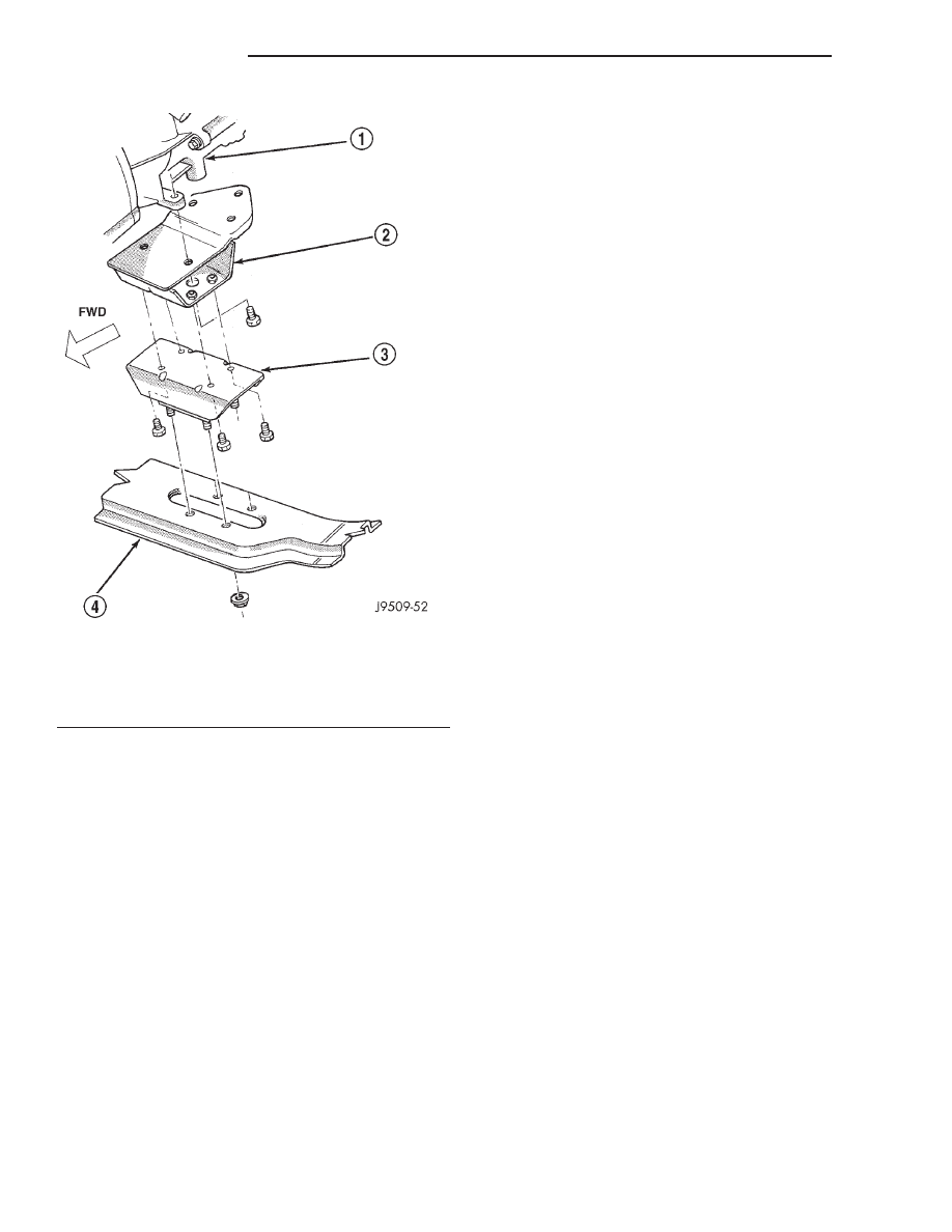
Fig. 39 Rear Insulator—4WD Vehicles

1 – AUTOMATIC TRANSMISSION
2 – INSULATOR BRACKET
3 – INSULATOR
4 – CROSSMEMBER

9 - 162

5.9L ENGINE

DN

REMOVAL AND INSTALLATION (Continued)

INTAKE MANIFOLD

REMOVAL

(1) Disconnect the battery negative cable.
(2) Drain the cooling system. Refer to COOLING

SYSTEM.

(3) Remove the A/C compressor. Refer to HEAT-

ING and AIR CONDITIONING.

(4) Remove the generator. Refer to CHARGING

SYSTEM.

(5) Remove the accessory drive bracket.
(6) Remove the air cleaner assembly and air inlet

hose.

(7) Perform the fuel pressure release procedure.

Refer to FUEL SYSTEM.

(8) Disconnect the fuel supply line from the fuel

rail. Refer to FUEL SYSTEM.

(9) Disconnect the accelerator linkage and, if so

equipped, the speed control and transmission kick-
down cables.

(10) Remove the distributor cap and wires.
(11) Disconnect the coil wires.
(12) Disconnect the coolant temperature sending

unit wire.

(13) Disconnect the heater hoses and bypass hose.
(14) Remove the closed crankcase ventilation and

evaporation control systems.

(15) Remove intake manifold bolts.
(16) Lift the intake manifold and throttle body out

of the engine compartment as an assembly.

(17) Remove and discard the flange side gaskets

and the front and rear cross-over gaskets.

(18) Remove the throttle body bolts and lift the

throttle body off the intake manifold (Fig. 40). Dis-
card the throttle body gasket.

INSTALLATION

(1) If the plenum pan was removed, position pan

gasket and pan.

(2) Install plenum pan retaining bolts. (Fig. 41).
(3) Tighten plenum pan mounting bolts as follows:
• Step 1. Tighten bolts to 5.4 N·m (24 in. lbs.)

• Step 2. Tighten bolts to 9.5 N·m (84 in. lbs.)

• Step 3. Check all bolts are at 9.5 N·m (84 in.

lbs.)

(4) Using a new gasket, install the throttle body

onto the intake manifold. Tighten the bolts to 23 N·m
(200 in. lbs.) torque.

(5) Apply a bead of Mopar Silicone Rubber Adhe-

sive Sealant, or equivalent, to the four corner joints.
The sealant bead height should be slightly higher
than the cross-over gaskets, approximately 5 mm (0.2
in). An excessive amount of sealant is not required to
ensure a leak proof seal, and an excessive amount of
sealant may reduce the effectiveness of the flange
gasket.

(6) Install the front and rear cross-over gaskets

onto the engine (Fig. 42).

(7) Install the flange gaskets. Ensure that the ver-

tical port alignment tab is resting on the deck face of
the block. Also the horizontal alignment tabs must be
in position with the mating cylinder head gasket tabs
(Fig. 43). The words MANIFOLD SIDE should be vis-
ible on the center of each flange gasket.

(8) Carefully lower intake manifold into position

on the cylinder block and cylinder heads. long studs
at the front and rear of the manifold will help to
align the intake manifold. After intake manifold is in

Fig. 40 Throttle Body Assembly

1 – FUEL RAIL ASSEMBLY
2 – FUEL RAIL MOUNTING BOLTS
3 – FUEL RAIL CONNECTING HOSES

Fig. 41 Plenum Pan Bolt Tightening Sequence

DN

5.9L ENGINE

9 - 163

REMOVAL AND INSTALLATION (Continued)

place, inspect to make sure seals are in place.
Remove alignment studs if used.

(9) The following torque sequence duplicates the

expected results of the automated assembly system
(Fig. 44).

• Step 1—Tighten bolts 1 thru 4, in sequence, to 8

N·m (72 in. lbs.) torque. Tighten in alternating steps
1.4 N·m (12 in. lbs.) torque at a time.

• Step 2—Tighten bolts 5 thru 12, in sequence, to

8 N·m (72 in. lbs.) torque.

• Step 3—Check that all bolts are tightened to 8

N·m (72 in. lbs.) torque.

• Step 4—Tighten all bolts, in sequence, to 16 N·m

(12 ft. lbs.) torque.

• Step 5—Check that all bolts are tightened to 16

N·m (12 ft. lbs.) torque.

(10) Install closed crankcase ventilation and evap-

oration control systems.

(11) Install the coil wires.
(12) Connect the coolant temperature sending unit

wire.

(13) Connect the heater hoses and bypass hose.
(14) Install distributor cap and wires.
(15) Connect the accelerator linkage and, if so

equipped, the speed control and transmission kick-
down cables.

(16) Install the fuel supply line to the fuel rail.
(17) Install the accessory drive bracket and A/C

compressor.

(18) Install the generator and accessory drive belt.

Tighten generator mounting bolt to 41 N·m (30 ft.
lbs.) torque.

(19) Install the air cleaner assembly and air inlet

hose.

(20) Fill cooling system.
(21) Connect the battery negative cable.

Fig. 42 Cross-Over Gaskets

1 – FRONT CROSS-OVER GASKET
2 – REAR CROSS-OVER GASKET

Fig. 43 Intake Manifold Flange Gasket Alignment

1 – FLANGE GASKET
2 – ALIGNMENT TABS
3 – CYLINDER HEAD GASKET

Fig. 44 Intake Manifold Bolt Tightening Sequence—

5.9L Engine

9 - 164

5.9L ENGINE

DN

REMOVAL AND INSTALLATION (Continued)

EXHAUST MANIFOLD

REMOVAL

(1) Disconnect the battery negative cable.
(2) Raise the vehicle.
(3) Remove the exhaust pipe to manifold nuts.
(4) Lower the vehicle.
(5) Remove three nuts, heat shield and washers

from the right side exhaust manifold, if necessary
(Fig. 45).

(6) Remove two nuts, heat shield and washers

from the left side exhaust manifold, if necessary (Fig.
46).

(7) Remove bolts, nuts and washers attaching

manifold to cylinder head.

(8) Remove manifold from the cylinder head.

INSTALLATION

CAUTION: If the studs came out with the nuts when
removing the exhaust manifold, install new studs.

(1) Position the exhaust manifolds on the two

studs located on the cylinder head. Install conical
washers and nuts on these studs (Fig. 47).

(2) Install new bolt and washer assemblies in the

remaining holes (Fig. 47). Start at the center arm
and work outward. Tighten the bolts and nuts to 24
N·m (18 ft. lbs.) torque.

(3) Position three washers, heat shield and nuts on

the right side exhaust manifold. Tighten nuts to 24
N·m (18 ft. lbs.).

(4) Position two washers, heat shield and nuts on

the left side exhaust manifold. Tighten nuts to 24
N·m (18 ft. lbs.).

(5) Raise the vehicle.

(6) Assemble the exhaust pipe to the exhaust man-

ifold and secure with bolts, nuts and washers.
Tighten these nuts to 27 N·m (20 ft. lbs.) torque.

(7) Lower the vehicle.
(8) Connect the battery negative cable.

CYLINDER HEAD COVER

A steel backed silicon gasket is used with the cyl-

inder head cover (Fig. 48). This gasket can be used
again.

REMOVAL

(1) Disconnect the negative cable from the battery.

Fig. 45 Exhaust Manifold Heat Shield—Right Side

1 – WASHER
2 – NUT AND WASHER
3 – EXHAUST MANIFOLD HEAT SHIELD

Fig. 46 Exhaust Manifold Heat Shield—Left Side

1 – WASHER
2 – NUT AND WASHER
3 – EXHAUST MANIFOLD HEAT SHIELD

Fig. 47 Exhaust Manifold Installation—5.9L Engine

1 – EXHAUST MANIFOLD (LEFT)
2 – BOLTS & WASHERS
3 – NUTS & WASHERS
4 – EXHAUST MANIFOLD (RIGHT)
5 – BOLTS & WASHERS

DN

5.9L ENGINE

9 - 165

REMOVAL AND INSTALLATION (Continued)


Content   ..  456  457  458  459   ..