Dodge Durango (DN). Manual - part 287


  Index      Dodge     Dodge Durango (DN) - service repair manual 2000 year


Search            


Content   ..  285  286  287  288   ..


Dodge Durango (DN). Manual - part 287


For complete circuit diagrams, see Group 8W -

Wiring Diagrams. Inspect the ground paths and con-
nections at the following locations:

• Blower motor

• Electric fuel pump

• Engine-to-body ground strap(s)

• Generator

• Ignition module

• Radio antenna base ground

• Radio receiver chassis ground wire or strap

• Wiper motor.
If the source of RFI or EMI noise is identified as a

component on the vehicle (i.e., generator, blower
motor, etc.), the ground path for that component
should be checked. If excessive resistance is found in
any ground circuit, clean, tighten, or repair the
ground circuits or connections to ground as required
before considering any component replacement.

For service and inspection of secondary ignition

components, refer to the Diagnosis and Testing sec-
tion of Group 8D - Ignition Systems. Inspect the fol-
lowing secondary ignition system components:

• Distributor cap and rotor

• Ignition coil

• Spark plugs

• Spark plug wire routing and condition.
Reroute the spark plug wires or replace the faulty

components as required.

If the source of the RFI or EMI noise is identified

as two-way mobile radio or telephone equipment,
check the equipment installation for the following:

• Power connections should be made directly to

the battery, and fused as closely to the battery as
possible.

• The antenna should be mounted on the roof or

toward the rear of the vehicle. Remember that mag-
netic antenna mounts on the roof panel can adversely
affect the operation of an overhead console compass,
if the vehicle is so equipped.

• The antenna cable should be fully shielded coax-

ial cable, should be as short as is practical, and
should be routed away from the factory-installed
vehicle wire harnesses whenever possible.

• The antenna and cable must be carefully

matched to ensure a low Standing Wave Ratio
(SWR).

Fleet vehicles are available with an extra-cost RFI-

suppressed Powertrain Control Module (PCM). This
unit reduces interference generated by the PCM on
some radio frequencies used in two-way radio com-
munications. However, this unit will not resolve com-
plaints of RFI in the commercial AM or FM radio
frequency ranges.

REMOVAL AND INSTALLATION

RADIO RECEIVER

WARNING: ON VEHICLES EQUIPPED WITH AIR-
BAGS,

REFER

TO

GROUP

8M

-

PASSIVE

RESTRAINT SYSTEMS BEFORE ATTEMPTING ANY
STEERING

WHEEL,

STEERING

COLUMN,

OR

INSTRUMENT PANEL COMPONENT DIAGNOSIS OR
SERVICE. FAILURE TO TAKE THE PROPER PRE-
CAUTIONS COULD RESULT IN ACCIDENTAL AIR-
BAG DEPLOYMENT AND POSSIBLE PERSONAL
INJURY.

REMOVAL

(1) Disconnect and isolate the battery negative

cable.

(2) Remove the cluster bezel from the instrument

panel. Refer to Cluster Bezel in the Removal and
Installation section of Group 8E - Instrument Panel
Systems for the procedures.

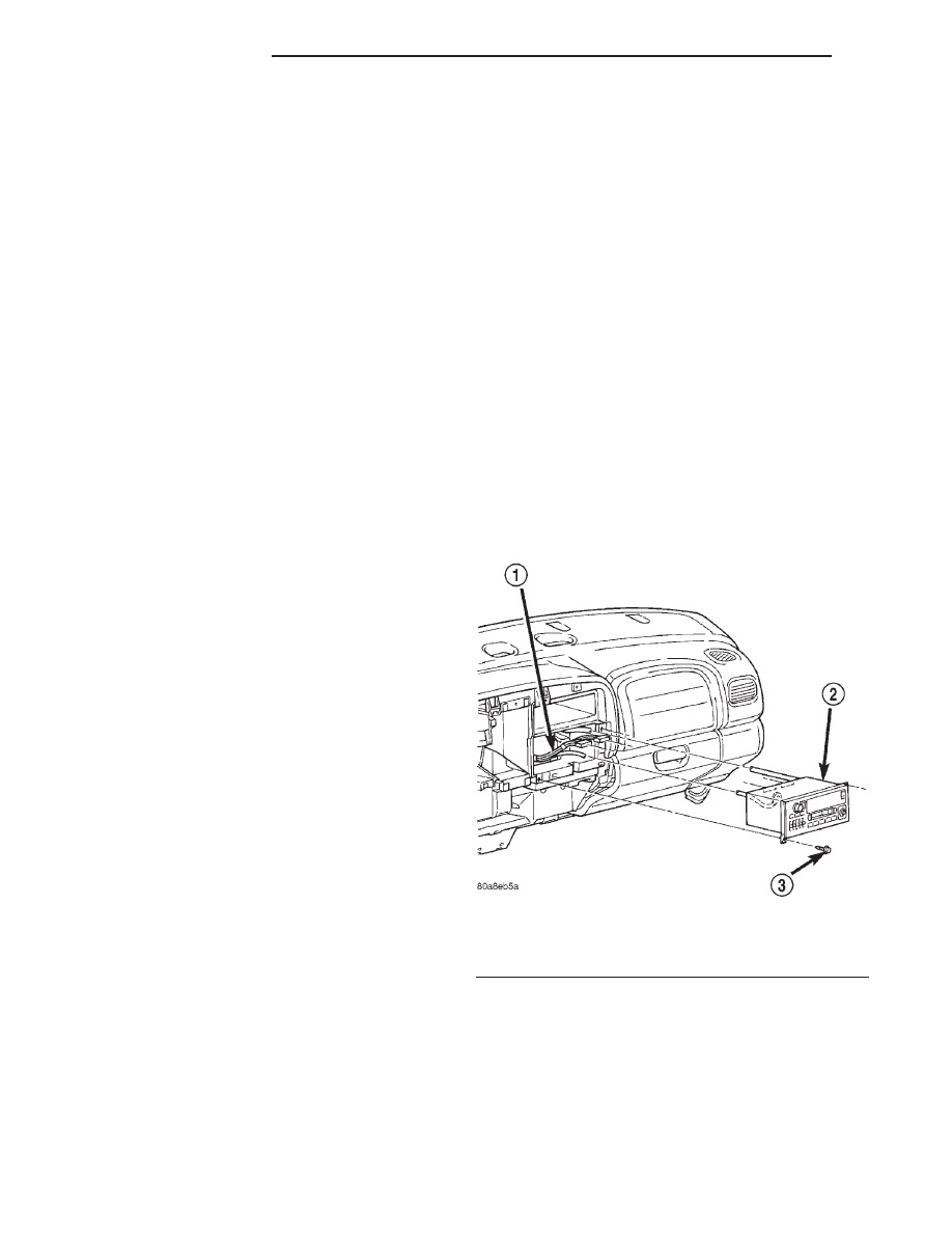
(3) Remove the two screws that secure the radio

receiver to the instrument panel (Fig. 4).

(4) Pull the radio receiver out from the instrument

panel far enough to access the instrument panel wire
harness connectors and the antenna coaxial cable
connector (Fig. 5).

(5) Disconnect the instrument panel wire harness

connectors and the antenna coaxial cable connector
from the receptacles on the rear of the radio receiver.

(6) Remove the radio receiver from the instrument

panel.

Fig. 4 Radio Receiver Remove/Install

1 – WIRE HARNESS
2 – RADIO
3 – SCREW

8F - 10

AUDIO SYSTEMS

DN

DIAGNOSIS AND TESTING (Continued)

INSTALLATION

(1) Position the radio receiver to the instrument

panel.

(2) Reconnect the instrument panel wire harness

connectors and the antenna coaxial cable connector
to the receptacles on the rear of the radio receiver.

(3) Position the radio receiver into the mounting

hole in the instrument panel.

(4) Install and tighten the two screws that secure

the radio receiver to the instrument panel. Tighten
the screws to 5 N·m (45 in. lbs.).

(5) Install the cluster bezel onto the instrument

panel. Refer to Cluster Bezel in the Removal and
Installation section of Group 8E - Instrument Panel
Systems for the procedures.

(6) Reconnect the battery negative cable.

REMOTE RADIO SWITCH

WARNING: ON VEHICLES EQUIPPED WITH AIR-
BAGS,

REFER

TO

GROUP

8M

-

PASSIVE

RESTRAINT SYSTEMS BEFORE ATTEMPTING ANY
STEERING

WHEEL,

STEERING

COLUMN,

OR

INSTRUMENT PANEL COMPONENT DIAGNOSIS OR
SERVICE. FAILURE TO TAKE THE PROPER PRE-
CAUTIONS COULD RESULT IN ACCIDENTAL AIR-
BAG DEPLOYMENT AND POSSIBLE PERSONAL
INJURY.

REMOVAL

(1) Disconnect and isolate the battery negative

cable.

(2) Remove the driver side airbag module from the

steering wheel. Refer to Driver Side Airbag Mod-
ule 
in the Removal and Installation section of Group
8M - Passive Restraint Systems for the procedures.

(3) Remove the speed control switch located on the

same side of the steering wheel as the remote radio
switch that is being serviced. Refer to Speed Con-
trol Switches 
in the Removal and Installation sec-
tion of Group 8H - Speed Control System for the
procedures.

(4) Disconnect the steering wheel wire harness

connector from the connector receptacle of the remote
radio switch (Fig. 6).

(5) Disengage the four remote radio switch latches

that secure the switch to the inside of the mounting
hole in the steering wheel rear trim cover.

Fig. 5 Radio Receiver Connections - Typical

1 – ANTENNA CABLE
2 – RADIO
3 – INSTRUMENT PANEL WIRING
4 – GROUND WIRE

Fig. 6 Remote Radio Switches Remove/Install

1 – STEERING WHEEL
2 – REMOTE RADIO SWITCH
3 – SPEED CONTROL SWITCH
4 – SCREW (2)
5 – DRIVER SIDE AIRBAG MODULE
6 – SPEED CONTROL SWITCH
7 – REAR TRIM COVER
8 – SCREW (2)

DN

AUDIO SYSTEMS

8F - 11

REMOVAL AND INSTALLATION (Continued)

(6) From the outside of the steering wheel rear

trim cover, remove the remote radio switch from the
trim cover mounting hole.

INSTALLATION

(1) Position the remote radio switch to the mount-

ing hole on the outside of the steering wheel rear
trim cover. Be certain that the connector receptacle is
oriented toward the bottom of the switch and pointed
toward the center of the steering wheel.

(2) Press firmly and evenly on the remote radio

switch until each of the switch latches is fully
engaged in the mounting hole of the steering wheel
rear trim cover.

(3) Reconnect the steering wheel wire harness con-

nector to the connector receptacle of the remote radio
switch.

(4) Install the speed control switch onto the steer-

ing wheel. Refer to Speed Control Switches in the
Removal and Installation section of Group 8H -
Speed Control System for the procedures.

(5) Install the driver side airbag module onto the

steering wheel. Refer to Driver Side Airbag Mod-
ule 
in the Removal and Installation section of Group
8M - Passive Restraint Systems for the procedures.

(6) Reconnect the battery negative cable.

SPEAKER

REMOVAL

FRONT DOOR UPPER SPEAKER

(1) Disconnect and isolate the battery negative

cable.

(2) Remove the trim panel from the front door.

Refer to Front Door Trim Panel in the Removal
and Installation section of Group 23 - Body for the
procedures.

(3) Disconnect the door wire harness connector

from the front door upper speaker wire harness con-
nector (Fig. 7).

(4) Remove the two screws that secure the front

door upper speaker to the back of the trim panel.

(5) Remove the front door upper speaker from the

trim panel.

FRONT DOOR LOWER SPEAKER

(1) Disconnect and isolate the battery negative

cable.

(2) Remove the trim panel from the front door.

Refer to Front Door Trim Panel in the Removal
and Installation section of Group 23 - Body for the
procedures.

(3) Remove the three screws that secure the

speaker to the front door inner panel (Fig. 8).

(4) Pull the speaker away from the mounting hole

in the front door inner panel far enough to access the
wire harness connector.

(5) Disconnect the front door wire harness connec-

tor from the speaker connector receptacle.

(6) Remove the speaker from the front door inner

panel.

Fig. 7 Front Door Upper Speaker Remove/Install

1 – POWER MIRROR SWITCH
2 – TWEETER
3 – POWER WINDOW SWITCH
4 – WIRE HARNESS CONNECTOR

Fig. 8 Front Door Lower Speaker Remove/Install

1 – SPEAKER
2 – SCREW
3 – CONNECTOR

8F - 12

AUDIO SYSTEMS

DN

REMOVAL AND INSTALLATION (Continued)

REAR DOOR SPEAKER

(1) Disconnect and isolate the battery negative

cable.

(2) Remove the trim panel from the rear door.

Refer to Rear Door Trim Panel in the Removal and
Installation section of Group 23 - Body for the proce-
dures.

(3) Remove the three screws that secure the

speaker to the rear door inner panel (Fig. 9).

(4) Pull the speaker away from the mounting hole

in the rear door inner panel far enough to access the
wire harness connector.

(5) Disconnect the rear door wire harness connec-

tor from the speaker connector receptacle.

(6) Remove the speaker from the rear door inner

panel.

INSTALLATION

FRONT DOOR UPPER SPEAKER

(1) Position the front door upper speaker to the

back of the trim panel.

(2) Install and tighten the two screws that secure

the front door upper speaker to the trim panel.
Tighten the screws to 2 N·m (17 in. lbs.).

(3) Reconnect the door wire harness connector to

the front door upper speaker wire harness connector.

(4) Install the trim panel onto the front door. Refer

to Front Door Trim Panel in the Removal and
Installation section of Group 23 - Body for the proce-
dures.

(5) Reconnect the battery negative cable.

FRONT DOOR LOWER SPEAKER

(1) Inspect the terminals in the speaker connector

receptacle and in the door wire harness connector for
corrosion. Clean or replace the terminals as required.

(2) Push a small amount of grease (Lithium

Extreme Pressure - Number 2 Grade or equivalent)
into the cavities of the door wire harness connector
for the speaker.

(3) Position the speaker to the front door inner

panel.

(4) Reconnect the front door wire harness connec-

tor to the speaker connector receptacle.

(5) Position the speaker into the mounting hole in

the front door inner panel.

(6) Install and tighten the three screws that secure

the speaker to the front door inner panel. Tighten
the screws to 2 N·m (17 in. lbs.).

(7) Install the trim panel onto the front door. Refer

to Front Door Trim Panel in the Removal and
Installation section of Group 23 - Body for the proce-
dures.

(8) Reconnect the battery negative cable.

REAR DOOR SPEAKER

(1) Inspect the terminals in the speaker connector

receptacle and in the door wire harness connector for
corrosion. Clean or replace the terminals as required.

(2) Push a small amount of multipurpose grease

(Lithium Extreme Pressure - Number 2 Grade or
equivalent) into the cavities of the door wire harness
connector for the speaker.

(3) Position the speaker to the rear door inner

panel.

(4) Reconnect the rear door wire harness connector

to the speaker connector receptacle.

(5) Position the speaker into the mounting hole in

the rear door inner panel.

(6) Install and tighten the three screws that secure

the speaker to the rear door inner panel. Tighten the
screws to 2 N·m (17 in. lbs.).

(7) Install the trim panel onto the rear door. Refer

to Rear Door Trim Panel in the Removal and
Installation section of Group 23 - Body for the proce-
dures.

(8) Reconnect the battery negative cable.

Fig. 9 Rear Door Speaker Remove/Install

1 – WIRE HARNESS CONNECTOR
2 – SPEAKER
3 – SCREW

DN

AUDIO SYSTEMS

8F - 13

REMOVAL AND INSTALLATION (Continued)


Content   ..  285  286  287  288   ..