Dodge Durango (DN). Manual - part 271


  Index      Dodge     Dodge Durango (DN) - service repair manual 2000 year


Search            


Content   ..  269  270  271  272   ..


Dodge Durango (DN). Manual - part 271


(2) Disconnect sensor pigtail harness from engine

wire harness. Sensor pigtail harness is clipped to
vehicle near its electrical connector.

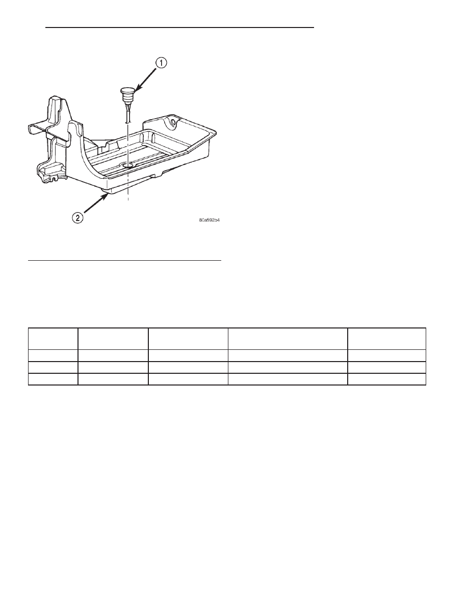
(3) Pry sensor straight up from battery tray

mounting hole.

INSTALLATION

(1) Feed pigtail harness through hole in top of bat-

tery tray and press sensor into top of battery tray.

(2) Connect pigtail harness.
(3) Install battery. Refer to Group 8A, Battery for

procedures.

SPECIFICATIONS

GENERATOR RATINGS

TYPE

PART NUMBER

RATED SAE AMPS

ENGINES

MINIMUM TEST

AMPS

DENSO

56041324AC

136

4.7L

100

DENSO

56027912AB

117

3.9L/5.2L/5.9L

90

DENSO

56027913AB

136

3.9L/5.2L/5.9L

100

TORQUE CHART

DESCRIPTION

TORQUE

Generator Mounting Bolt—

3.9L/5.2L/5.9L Engines . . . . . 41 N·m (30 ft. lbs.)

Generator Pivot Bolt—

3.9L/5.2L/5.9L Engines . . . . . 41 N·m (30 ft. lbs.)

Generator Vertical Mounting Bolt—

4.7L V–8 Engine . . . . . . . . . . 55 N·m (40 ft. lbs.)

Generator (long) Horizontal Mounting Bolt—

4.7L V–8 Engine . . . . . . . . . . 55 N·m (40 ft. lbs.)

Generator (short) Horizontal Mounting Bolt—

4.7L V–8 Engine . . . . . . . . . . 74 N·m (55 ft. lbs.)

Generator B+ Output Cable

Terminal Nut . . . . . . . . . . . . 8.5 N·m (75 in. lbs.)

Fig. 5 Battery Temperature Sensor Location

1 – BATTERY TEMPERATURE SENSOR
2 – BATTERY TRAY

DN

CHARGING SYSTEM

8C - 5

REMOVAL AND INSTALLATION (Continued)

IGNITION SYSTEM

TABLE OF CONTENTS

page

page

DESCRIPTION AND OPERATION

IGNITION SYSTEM . . . . . . . . . . . . . . . . . . . . . . . . 1
DISTRIBUTOR—5.2L/5.9L V-8 ENGINE . . . . . . . . 1
SPARK PLUGS . . . . . . . . . . . . . . . . . . . . . . . . . . . 2
SPARK PLUG CABLES . . . . . . . . . . . . . . . . . . . . . 2
IGNITION COIL (EXCEPT 4.7L ENGINE). . . . . . . . 2
IGNITION COIL—4.7L ENGINE. . . . . . . . . . . . . . . 3
CRANKSHAFT POSITION SENSOR—5.2/5.9L

V-8 ENGINE . . . . . . . . . . . . . . . . . . . . . . . . . . . . 3

CRANKSHAFT POSITION SENSOR—4.7L

ENGINE . . . . . . . . . . . . . . . . . . . . . . . . . . . . . . . 3

CAMSHAFT POSITION SENSOR. . . . . . . . . . . . . . 4
CAMSHAFT POSITION SENSOR—4.7L

ENGINE . . . . . . . . . . . . . . . . . . . . . . . . . . . . . . . 5

IGNITION SWITCH AND KEY LOCK

CYLINDER . . . . . . . . . . . . . . . . . . . . . . . . . . . . . 5

DIAGNOSIS AND TESTING

DISTRIBUTOR CAP. . . . . . . . . . . . . . . . . . . . . . . . 6
DISTRIBUTOR ROTOR . . . . . . . . . . . . . . . . . . . . . 6
SPARK PLUG CABLES . . . . . . . . . . . . . . . . . . . . . 7
SPARK PLUG CONDITIONS . . . . . . . . . . . . . . . . . 8
IGNITION SWITCH AND KEY LOCK

CYLINDER . . . . . . . . . . . . . . . . . . . . . . . . . . . . 10

REMOVAL AND INSTALLATION

SPARK PLUG CABLES . . . . . . . . . . . . . . . . . . . . 11

SPARK PLUGS . . . . . . . . . . . . . . . . . . . . . . . . . . 11
IGNITION COIL—3.9/5.2/5.9L ENGINES . . . . . . 12
IGNITION COIL—4.7L ENGINE. . . . . . . . . . . . . . 13
CRANKSHAFT POSITION SENSOR—3.9/5.2/

5.9L ENGINES . . . . . . . . . . . . . . . . . . . . . . . . . 14

CRANKSHAFT POSITION SENSOR—4.7L V-8

ENGINE . . . . . . . . . . . . . . . . . . . . . . . . . . . . . . 14

CAMSHAFT POSITION SENSOR. . . . . . . . . . . . . 15
CAMSHAFT POSITION SENSOR—4.7L

ENGINE . . . . . . . . . . . . . . . . . . . . . . . . . . . . . . 15

DISTRIBUTORS—3.9/5.2/5.9L ENGINES . . . . . . 16
IGNITION SWITCH AND KEY CYLINDER . . . . . . 17
COLUMN SHIFT INTERLOCK . . . . . . . . . . . . . . . 21

SPECIFICATIONS

IGNITION TIMING. . . . . . . . . . . . . . . . . . . . . . . . 21
ENGINE FIRING ORDER—5.2L/5.9L V-8

ENGINES . . . . . . . . . . . . . . . . . . . . . . . . . . . . . 21

ENGINE FIRING ORDER—4.7L V-8 ENGINE . . . 21
SPARK PLUGS . . . . . . . . . . . . . . . . . . . . . . . . . . 22
SPARK PLUG CABLE RESISTANCE . . . . . . . . . . 22
IGNITION COIL RESISTANCE—EXCEPT 4.7L

ENGINE . . . . . . . . . . . . . . . . . . . . . . . . . . . . . . 22

IGNITION COIL RESISTANCE—4.7L V-8

ENGINE . . . . . . . . . . . . . . . . . . . . . . . . . . . . . . 22

TORQUE CHART . . . . . . . . . . . . . . . . . . . . . . . . . 22

DESCRIPTION AND OPERATION

IGNITION SYSTEM

DESCRIPTION

Two different ignition systems are used. One type

of system is for the 5.2L/5.9L V-8 engine. The other is
for the 4.7L V-8 engine.

The ignition systems used on 5.2L/5.9L V-8 engines

are basically identical using a conventional distribu-
tor and remotely mounted coil. The 4.7L V-8 engine
does not use a distributor and has 8 separate coils.

OPERATION

The ignition system is controlled by the Powertrain

Control Module (PCM) on all engines.

The ignition system consists of:
• Spark Plugs

• Ignition Coil(s)

• Secondary Ignition Cables (5.2L/5.9L engines)

• Distributor (contains rotor and camshaft position

sensor) (5.2L/5.9L engines)

• Powertrain Control Module (PCM)

• Crankshaft Position and Camshaft Position Sen-

sors

• The MAP, TPS, IAC and ECT also have an effect

on the control of the ignition system.

DISTRIBUTOR—5.2L/5.9L V-8 ENGINE

DESCRIPTION

The 5.2L/5.9L V-8 engine is equipped with a cam-

shaft driven mechanical distributor (Fig. 1) contain-
ing a shaft driven distributor rotor. All distributors
are equipped with an internal camshaft position (fuel
sync) sensor (Fig. 1).

DN

IGNITION SYSTEM

8D - 1

OPERATION

The camshaft position sensor provides fuel injec-

tion synchronization and cylinder identification.

The distributor does not have built in centrifugal

or vacuum assisted advance. Base ignition timing
and all timing advance is controlled by the Power-
train Control Module (PCM). Because ignition timing
is controlled by the PCM, base ignition timing is
not adjustable.

The distributor is held to the engine in the conven-

tional method using a holddown clamp and bolt.
Although the distributor can be rotated, it will
have no effect on ignition timing.

All distributors contain an internal oil seal that

prevents oil from entering the distributor housing.
The seal is not serviceable.

SPARK PLUGS

DESCRIPTION

All engines use resistor type spark plugs. 4.7L V-8

engines are equipped with “fired in suppressor seal”
type spark plugs using a copper core ground elec-
trode.

Because of the use of an aluminum cylinder head

on the 4.7L engine, spark plug torque is very critical.

To prevent possible pre-ignition and/or mechanical

engine damage, the correct type/heat range/number
spark plug must be used.

OPERATION

Remove the spark plugs and examine them for

burned electrodes and fouled, cracked or broken por-
celain insulators. Keep plugs arranged in the order
in which they were removed from the engine. A sin-

gle plug displaying an abnormal condition indicates
that a problem exists in the corresponding cylinder.
Replace spark plugs at the intervals recommended in
Group O, Lubrication and Maintenance.

Spark plugs that have low mileage may be cleaned

and reused if not otherwise defective, carbon or oil
fouled. Also refer to Spark Plug Conditions.

CAUTION: Never use a motorized wire wheel brush
to clean the spark plugs. Metallic deposits will
remain on the spark plug insulator and will cause
plug misfire.

SPARK PLUG CABLES

DESCRIPTION

Spark plug cables are sometimes referred to as sec-

ondary ignition wires.

OPERATION

The spark plug cables transfer electrical current

from the ignition coil(s) and/or distributor, to individ-
ual spark plugs at each cylinder. The resistive spark
plug cables are of nonmetallic construction. The
cables provide suppression of radio frequency emis-
sions from the ignition system.

IGNITION COIL (EXCEPT 4.7L ENGINE)

DESCRIPTION

A single ignition coil is used. The coil is not oil

filled. The coil windings are embedded in an epoxy
compound. This provides heat and vibration resis-
tance that allows the coil to be mounted on the
engine.

OPERATION

The Powertrain Control Module (PCM) opens and

closes the ignition coil ground circuit for ignition coil
operation.

Battery voltage is supplied to the ignition coil pos-

itive terminal from the ASD relay. If the PCM does
not see a signal from the crankshaft and camshaft
sensors (indicating the ignition key is ON but the
engine is not running), it will shut down the ASD cir-
cuit.

Base ignition timing is not adjustable on any

engine. By controlling the coil ground circuit, the
PCM is able to set the base timing and adjust the
ignition timing advance. This is done to meet chang-
ing engine operating conditions.

Fig. 1 Distributor and Camshaft Position Sensor

1 – SYNC SIGNAL GENERATOR
2 – CAMSHAFT POSITION SENSOR
3 – PULSE RING
4 – DISTRIBUTOR ASSEMBLY

8D - 2

IGNITION SYSTEM

DN

DESCRIPTION AND OPERATION (Continued)

IGNITION COIL—4.7L ENGINE

DESCRIPTION

The 4.7L V–8 engine uses 8 dedicated, and individ-

ually fired coil (Fig. 2) for each spark plug. Each coil
is mounted directly to the top of each spark plug
(Fig. 3).

OPERATION

Battery voltage is supplied to the 8 ignition coils

from the ASD relay. The Powertrain Control Module
(PCM) opens and closes each ignition coil ground cir-
cuit at a determined time for ignition coil operation.

Base ignition timing is not adjustable. By con-

trolling the coil ground circuit, the PCM is able to set
the base timing and adjust the ignition timing
advance. This is done to meet changing engine oper-
ating conditions.

The ignition coil is not oil filled. The windings are

embedded in an epoxy compound. This provides heat
and vibration resistance that allows the ignition coil
to be mounted on the engine.

Because of coil design, spark plug cables (second-

ary cables) are not used.

CRANKSHAFT POSITION SENSOR—5.2/5.9L
V-8 ENGINE

DESCRIPTION

The Crankshaft Position (CKP) sensor is located

near the outer edge of the flywheel (starter ringear).

OPERATION

Engine speed and crankshaft position are provided

through the CKP sensor. The sensor generates pulses
that are the input sent to the Powertrain Control
Module (PCM). The PCM interprets the sensor input
to determine the crankshaft position. The PCM then
uses this position, along with other inputs, to deter-
mine injector sequence and ignition timing.

The sensor is a hall effect device combined with an

internal magnet. It is also sensitive to steel within a
certain distance from it.

On 5.2/5.9L V-8 engines, the flywheel/drive plate

has 8 single notches, spaced every 45 degrees, at its
outer edge (Fig. 4).

The notches cause a pulse to be generated when

they pass under the sensor. The pulses are the input
to the PCM. For each engine revolution, there are 8
pulses generated on V-8 engines.

The engine will not operate if the PCM does not

receive a CKP sensor input.

CRANKSHAFT POSITION SENSOR—4.7L
ENGINE

DESCRIPTION

The Crankshaft Position Sensor (CKP) is mounted

into the right-rear side of the engine block (Fig. 5).

Fig. 2 Ignition Coil—4.7L Engine

1 – O-RING
2 – IGNITION COIL
3 – ELECTRICAL CONNECTOR

Fig. 3 Ignition Coil Location—4.7L Engine

1 – IGNITION COIL
2 – COIL ELECTRICAL CONNECTOR
3 – COIL MOUNTING STUD/NUT

DN

IGNITION SYSTEM

8D - 3

DESCRIPTION AND OPERATION (Continued)


Content   ..  269  270  271  272   ..