Dodge Durango (DN). Manual - part 255


  Index      Dodge     Dodge Durango (DN) - service repair manual 2000 year


Search            


Content   ..  253  254  255  256   ..


Dodge Durango (DN). Manual - part 255


ACCESSORY DRIVE BELT DIAGNOSIS

VISUAL DIAGNOSIS

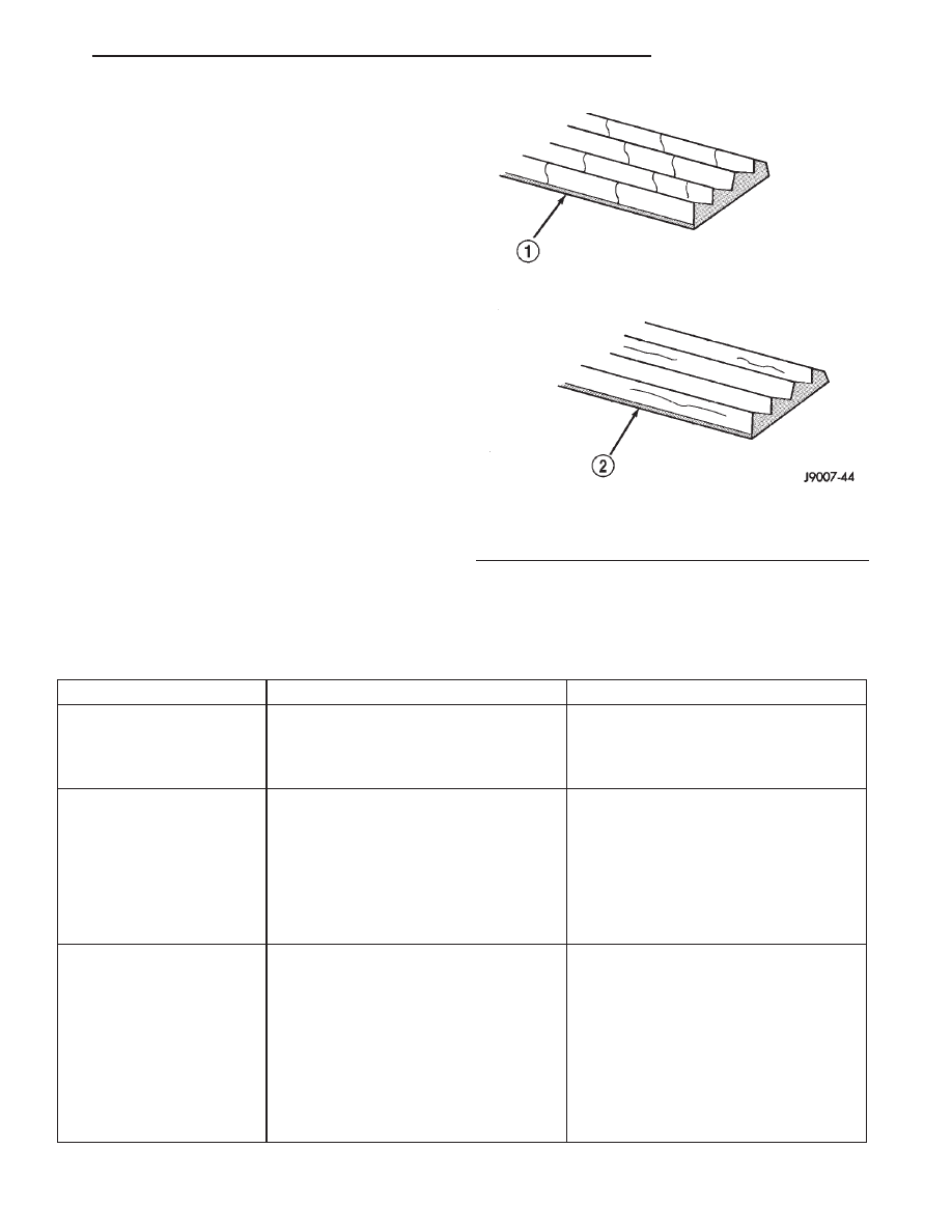
When diagnosing serpentine accessory drive belts,

small cracks that run across the ribbed surface of the
belt from rib to rib (Fig. 23), are considered normal.
These are not a reason to replace the belt. However,
cracks running along a rib (not across) are not nor-
mal. Any belt with cracks running along a rib must
be replaced (Fig. 23). Also replace the belt if it has
excessive wear, frayed cords or severe glazing.

Refer to the Accessory Drive Belt Diagnosis charts

for further belt diagnosis.

NOISE DIAGNOSIS

Noises generated by the accessory drive belt are

most noticeable at idle. Before replacing a belt to
resolve a noise condition, inspect all of the accessory
drive pulleys for alignment, glazing, or excessive end
play.

ACCESSORY DRIVE BELT DIAGNOSIS CHART

CONDITION

POSSIBLE CAUSES

CORRECTION

RIB CHUNKING (One or
more ribs has separated
from belt body)

1. Foreign objects imbedded in pulley
grooves.

1. Remove foreign objects from pulley
grooves. Replace belt.

2. Installation damage

2. Replace belt

RIB OR BELT WEAR

1. Pulley misaligned

1. Align pulley(s)

2. Abrasive environment

2. Clean pulley(s). Replace belt if
necessary

3. Rusted pulley(s)

3. Clean rust from pulley(s)

4. Sharp or jagged pulley groove tips

4. Replace pulley. Inspect belt.

5. Belt rubber deteriorated

5. Replace belt

BELT SLIPS

1. Belt slipping because of insufficient
tension

1. Inspect/Replace tensioner if
necessary

2. Belt or pulley exposed to substance
that has reduced friction (belt dressing,
oil, ethylene glycol)

2. Replace belt and clean pulleys

3. Driven component bearing failure
(seizure)

3. Replace faulty component or bearing

4. Belt glazed or hardened from heat
and excessive slippage

4. Replace belt.

Fig. 23 Belt Wear Patterns

1 – NORMAL CRACKS BELT OK
2 – NOT NORMAL CRACKS REPLACE BELT

DN

COOLING SYSTEM

7 - 19

DIAGNOSIS AND TESTING (Continued)

CONDITION

POSSIBLE CAUSES

CORRECTION

LONGITUDAL BELT
CRACKING

1. Belt has mistracked from pulley
groove

1. Replace belt

2. Pulley groove tip has worn away
rubber to tensile member

2. Replace belt

9

GROOVE JUMPING”

(Belt does not maintain
correct position on pulley)

1. Incorrect belt tension

1. Inspect/Replace tensioner if
necessary

2. Pulley(s) not within design tolerance

2. Replace pulley(s)

3. Foreign object(s) in grooves

3. Remove foreign objects from grooves

4. Pulley misalignment

4. Align component

5. Belt cordline is broken

5. Replace belt

BELT BROKEN
(Note: Identify and correct
problem before new belt is
installed)

1. Incorrect belt tension

1. Replace Inspect/Replace tensioner if
necessary

2. Tensile member damaged during belt
installation

2. Replace belt

3. Severe misalignment

3. Align pulley(s)

4. Bracket, pulley, or bearing failure

4. Replace defective component and
belt

NOISE
(Objectionable squeal,
squeak, or rumble is heard
or felt while drive belt is in
operation)

1. Incorrect belt tension

1. Inspect/Replace tensioner if
necessary

2. Bearing noise

2. Locate and repair

3. Belt misalignment

3. Align belt/pulley(s)

4. Belt to pulley mismatch

4. Install correct belt

5. Driven component induced vibration

5. Locate defective driven component
and repair

TENSION SHEETING
FABRIC FAILURE
(Woven fabric on outside,
circumference of belt has
cracked or separated from
body of belt)

1. Tension sheeting contacting
stationary object

1. Correct rubbing condition

2. Excessive heat causing woven fabric
to age

2. Replace belt

3. Tension sheeting splice has fractured

3. Replace belt

CORD EDGE FAILURE
(Tensile member exposed
at edges of belt or
separated from belt body)

1. Incorrect belt tension

1. Inspect/Replace tensioner if
necessary

2. Belt contacting stationary object

2. Replace belt

3. Pulley(s) out of tolerance

3. Replace pulley

4. Insufficient adhesion between tensile
member and rubber matrix

4. Replace belt

7 - 20

COOLING SYSTEM

DN

DIAGNOSIS AND TESTING (Continued)

THERMOSTAT—GAS ENGINES

ON-BOARD DIAGNOSTICS

All gasoline powered models are equipped with

On-Board Diagnostics for certain cooling system com-
ponents. Refer to On-Board Diagnostics (OBD) in the
Diagnosis section of this group for additional infor-
mation. If the powertrain control module (PCM)
detects low engine coolant temperature, it will record
a Diagnostic Trouble Code (DTC) in the PCM mem-
ory. Do not change a thermostat for lack of heat as
indicated by the instrument panel gauge or by poor
heater performance unless a DTC is present. Refer to
the Diagnosis section of this group for other probable
causes. For other DTC numbers, refer to On-Board
Diagnostics in the General Diagnosis section of
Group 25, Emission Systems.

The DTC can also be accessed through the DRB

scan tool. Refer to the appropriate Powertrain Diag-
nostic Procedures manual for diagnostic information
and operation of the DRB scan tool.

RADIATOR CAP-TO-FILLER NECK SEAL—
PRESSURE RELIEF CHECK

The pressure cap upper gasket (seal) pressure

relief can be tested by removing overflow hose from
radiator filler neck nipple. Attach hose of pressure
tester tool 7700 (or equivalent) to nipple. It will be
necessary to disconnect hose from its adapter for
filler neck. Pump air into radiator. The pressure cap
upper gasket should relieve at 69-124 kPa (10-18 psi)
and hold pressure at a minimum of 55 kPa (8 psi).

WARNING: THE

WARNING

WORDS

—DO

NOT

OPEN HOT— ON RADIATOR PRESSURE CAP, ARE
A SAFETY PRECAUTION. WHEN HOT, PRESSURE
BUILDS UP IN COOLING SYSTEM. TO PREVENT
SCALDING OR INJURY, RADIATOR CAP SHOULD
NOT BE REMOVED WHILE SYSTEM IS HOT AND/OR
UNDER PRESSURE.

Do not remove radiator cap at any time except for

the following purposes:

(1) Check and adjust antifreeze freeze point.
(2) Refill system with new antifreeze.
(3) Conducting service procedures.
(4) Checking for vacuum leaks.

WARNING: IF VEHICLE HAS BEEN RUN RECENTLY,
WAIT AT LEAST 15 MINUTES BEFORE REMOVING
RADIATOR CAP. WITH A RAG, SQUEEZE RADIATOR
UPPER HOSE TO CHECK IF SYSTEM IS UNDER
PRESSURE. PLACE A RAG OVER CAP AND WITH-
OUT PUSHING CAP DOWN, ROTATE IT COUNTER-
CLOCKWISE TO FIRST STOP. ALLOW FLUID TO
ESCAPE

THROUGH

THE

COOLANT

RESERVE/

OVERFLOW

HOSE

INTO

RESERVE/OVERFLOW

TANK. SQUEEZE RADIATOR UPPER HOSE TO
DETERMINE

WHEN

PRESSURE

HAS

BEEN

RELEASED. WHEN COOLANT AND STEAM STOP
BEING PUSHED INTO TANK AND SYSTEM PRES-
SURE DROPS, REMOVE RADIATOR CAP COM-
PLETELY.

RADIATOR CAP—PRESSURE TESTING

Remove cap from radiator. Be sure that sealing

surfaces are clean. Moisten rubber gasket with water
and install cap on pressure tester 7700 or an equiv-
alent (Fig. 24).

Operate tester pump to bring pressure to 117 kPa

(17 psi) on gauge. If pressure cap fails to hold pres-
sure of at least 110 kPa (16 psi) replace cap. Refer to
following CAUTION.

The pressure cap may test properly while posi-

tioned on tool 7700 (or equivalent). It may not hold
pressure or vacuum when installed on radiator. If so,
inspect radiator filler neck and cap’s top gasket for
damage. Also inspect for dirt or distortion that may
prevent cap from sealing properly.

Fig. 24 Pressure Testing Radiator Cap—Typical

1 – PRESSURE CAP
2 – TYPICAL COOLING SYSTEM PRESSURE TESTER

DN

COOLING SYSTEM

7 - 21

DIAGNOSIS AND TESTING (Continued)

CAUTION: Radiator pressure testing tools are very
sensitive to small air leaks, which will not cause
cooling system problems. A pressure cap that does
not have a history of coolant loss should not be
replaced just because it leaks slowly when tested
with this tool. Add water to tool. Turn tool upside
down and recheck pressure cap to confirm that cap
needs replacement.

COOLANT—LOW LEVEL AERATION

If the coolant level in the radiator drops below the

top of the radiator core tubes, air will enter the sys-
tem.

Low coolant level can cause the thermostat pellet

to be suspended in air instead of coolant. This will
cause the thermostat to open later, which in turn
causes higher coolant temperature. Air trapped in
cooling system also reduces the amount of coolant
circulating in the heater core. This may result in low
heat output.

COOLING SYSTEM—DEAERATION

As the engine operates, any air trapped in cooling

system gathers under the radiator cap. The next time
the engine is operated, thermal expansion of coolant
will push any trapped air past radiator cap into the
coolant reserve/overflow tank. Here it escapes to the
atmosphere into the tank. When the engine cools
down the coolant, it will be drawn from the reserve/
overflow tank into the radiator to replace any
removed air.

SERVICE PROCEDURES

COOLANT—ROUTINE LEVEL CHECK

NOTE: Do not remove radiator cap for routine cool-
ant level inspections. The coolant level can be
checked at coolant recovery bottle (Fig. 25).

The coolant reserve/overflow system provides a

quick method for determining coolant level without
removing radiator pressure cap. With engine not run-
ning, open the coolant recovery bottle cap and
remove coolant level indicator dipstick to observe
coolant level in coolant recovery bottle. The coolant
level should be between ADD and FULL marks. If
the coolant level is at or below the ADD mark, fill
the recovery bottle with a 50/50 mixture of antifreeze
and water ONE QUART AT A TIME. Repeat this pro-
cedure until the coolant level is at the FULL mark.

COOLANT SERVICE

For cooling system flush and fill maintenance

intervals, refer to Group 0, Lubrication and Mainte-
nance.

COOLANT

DESCRIPTION

ETHYLENE-GLYCOL MIXTURES

CAUTION: Richer antifreeze mixtures cannot be
measured with normal field equipment and can
cause problems associated with 100 percent ethyl-
ene-glycol.

The required ethylene-glycol (antifreeze) and water

mixture depends upon the climate and vehicle oper-
ating conditions. The recommended mixture of 50/50
ethylene-glycol and water will provide protection
against freezing to -37 deg. C (-35 deg. F). The anti-
freeze concentration must always be a minimum of
44 percent, year-round in all climates. If percentage
is lower than 44 percent, engine parts may be
eroded by cavitation, and cooling system com-
ponents may be severely damaged by corrosion.
Maximum protection against freezing is provided
with a 68 percent antifreeze concentration, which
prevents freezing down to -67.7 deg. C (-90 deg. F). A

Fig. 25 Coolant Recovery Bottle Location

1 – RADIATOR
2 – WASHER FLUID RESERVOIR
3 – COOLANT OVERFLOW/RESERVOIR
4 – FAN SHROUD (UPPER)
5 – SCREW
6 – INTERLOCKING PINS
7 – FAN SHROUD (LOWER)

7 - 22

COOLING SYSTEM

DN

DIAGNOSIS AND TESTING (Continued)


Content   ..  253  254  255  256   ..