Dodge Durango (DN). Manual - part 254
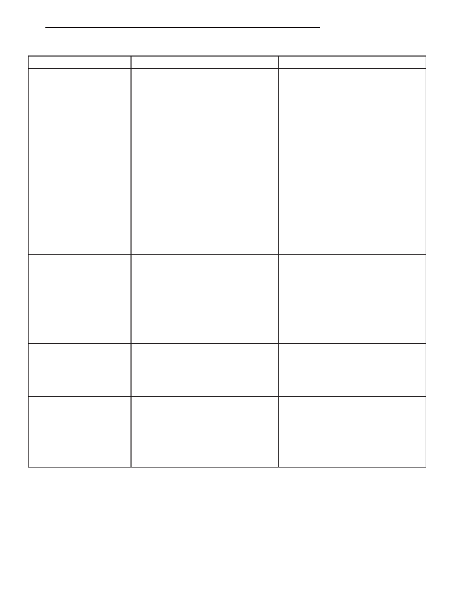
CONDITION
POSSIBLE CAUSES
CORRECTION
INADEQUATE HEATER
PERFORMANCE.
THERMOSTAT FAILED IN
OPEN POSITION
1. Has a Diagnostic trouble Code (DTC)
been set?
1. Refer to Group 25, Emissions for
correct procedures and replace
thermostat if necessary
2. Coolant level low
2. Refer to Cooling System-Testing For
Leaks in this group.
3. Obstructions in heater hose/fittings
3. Remove heater hoses at both ends
and check for obstructions
4. Heater hose kinked
4. Locate kinked area and repair as
necessary
5. Water pump is not pumping water
to/through the heater core. When the
engine is fully warmed up, both heater
hoses should be hot to the touch. If only
one of the hoses is hot, the water pump
may not be operating correctly or the
heater core may be plugged. Accessory
drive belt may be slipping causing poor
water pump operation.
5. Refer to Water Pump in this group. If
a slipping belt is detected, refer to
Accessory Drive Belts in this group. If
heater core obstruction is detected, refer
to Group 24, Heating and Air
Conditioning.
STEAM IS COMING FROM
THE FRONT OF VEHICLE
NEAR THE GRILL AREA
WHEN WEATHER IS WET,
ENGINE IS WARMED UP
AND RUNNING, AND
VEHICLE IS STATIONARY.
TEMPERATURE GAUGE
IS IN NORMAL RANGE
1. During wet weather, moisture (snow,
ice or rain condensation) on the radiator
will evaporate when the thermostat
opens. This opening allows heated
water into the radiator. When the
moisture contacts the hot radiator,
steam may be emitted. This usually
occurs in cold weather with no fan or
airflow to blow it away.
1. Occasional steam emitting from this
area is normal. No repair is necessary.
COOLANT COLOR
1. Coolant color is not necessarily an
indication of adequate corrosion or
temperature protection. Do not rely on
coolant color for determining condition
of coolant.
1. Refer to Coolant in this group for
coolant concentration information. Adjust
coolant mixture as necessary.
COOLANT LEVEL
CHANGES IN COOLANT
RESERVE/OVERFLOW
TANK. TEMPERATURE
GAUGE IS IN NORMAL
RANGE
1. Level changes are to be expected as
coolant volume fluctuates with engine
temperature. If the level in the tank was
between the FULL and ADD marks at
normal operating temperature, the level
should return to within that range after
operation at elevated temperatures.
1. A normal condition. No repair is
necessary.
ELECTRIC COOLING FAN
The powertrain control module (PCM) will set a
diagnostic trouble code (DTC) in memory if it detects
a problem in the electric cooling fan relay or circuit.
Refer to On-Board Diagnostics in Group 25, Emission
Control Systems for more information on accessing a
DTC.
The DTC can also be accessed through the DRB
scan tool. Refer to the appropriate Powertrain Diag-
nostic Procedures manual for diagnostic information
and operation of the DRB scan tool.
RADIATOR FAN MOTOR INOPERATIVE
Equipment Required:
• DRB Scan Tool
• Volt/Ohm meter
• Wiring Diagrams section of this manual
DN
COOLING SYSTEM
7 - 15
DIAGNOSIS AND TESTING (Continued)