Dodge Durango (DN). Manual - part 249


  Index      Dodge     Dodge Durango (DN) - service repair manual 2000 year


Search            


Content   ..  247  248  249  250   ..


Dodge Durango (DN). Manual - part 249


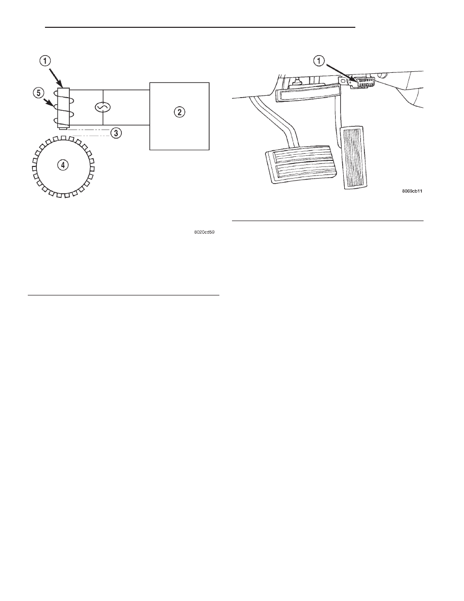
The assembly plant performs a “Rolls Test” on

every vehicle that leaves the assembly plant. One of
the test performed is a test of the WSS. To properly
test the sensor, the assembly plant connects test
equipment to the Data Link Connector (DLC). This
connector is located to the right of the steering col-
umn and attached to the lower portion of the instru-
ment panel (Fig. 4). The rolls test terminal is spliced
to the WSS circuit. The vehicle is then driven on a
set of rollers and the WSS output is monitored for
proper operation.

ABS WARNING LAMP

DESCRIPTION

The amber ABS warning lamp and red warning

lamp are located in the instrument cluster. The
amber ABS warning lamp illuminates at start-up to
perform a self check. The lamp goes out when the
self check program determines the system is operat-
ing normal. The red brake warning lamp is used to
alert the driver of a hydraulic fault or that the park-
ing brake is applied.

OPERATION

If an ABS component exhibits a fault the CAB will

illuminate the ABS warning lamp and register a
trouble code in the microprocessor. The lamp is con-
trolled by the CAB. The CAB controls the lamp send-
ing a message to the instrument cluster.

If red warning lamp is illuminate with the amber

warning lamp, this may indicate a electronic brake
distribution fault.

The red warning lamp will illuminate if an ABS

component exhibits a fault and the amber lamp is
burned out.

DIAGNOSIS AND TESTING

ANTILOCK BRAKES

The ABS brake system performs several self-tests

every time the ignition switch is turned on and the
vehicle is driven. The CAB monitors the systems
input and output circuits to verify the system is oper-
ating correctly. If the on board diagnostic system
senses that a circuit is malfunctioning the system
will set a trouble code in its memory.

NOTE: An audible noise may be heard during the
self-test. This noise should be considered normal.

NOTE: The MDS or DRB III scan tool is used to
diagnose the ABS system. For additional informa-
tion refer to the Antilock Brake section in Group
8W. For test procedures refer to the Chassis Diag-
nostic Manual.

Fig. 3 Operation of the Wheel Speed Sensor

1 – MAGNETIC CORE
2 – CAB
3 – AIR GAP
4 – EXCITER RING
5 – COIL

Fig. 4 Data Link Connector - Typical

1 – 16–WAY DATA LINK CONNECTOR

DN

BRAKES

5 - 43

DESCRIPTION AND OPERATION (Continued)

SERVICE PROCEDURES

BLEEDING ABS BRAKE SYSTEM

ABS system bleeding requires conventional bleed-

ing methods plus use of the DRB scan tool. The pro-
cedure involves performing a base brake bleeding,
followed by use of the scan tool to cycle and bleed the
HCU pump and solenoids. A second base brake bleed-
ing procedure is then required to remove any air
remaining in the system.

(1) Perform base brake bleeding. Refer to base

brake section for procedure.

(2) Connect scan tool to the Data Link Connector.
(3) Select ANTILOCK BRAKES, followed by MIS-

CELLANEOUS, then BLEED BRAKES. Follow the
instructions displayed. When scan tool displays TEST
COMPLETE, disconnect scan tool and proceed.

(4) Perform base brake bleeding a second time.

Refer to base brake section for procedure.

(5) Top off master cylinder fluid level and verify

proper brake operation before moving vehicle.

REMOVAL AND INSTALLATION

CONTROLLER ANTILOCK BRAKES

NOTE: If the CAB needs to be replaced, the rear axle
type and tire revolutions per mile must be programed
into the new CAB. For axle type refer to Group 3 Dif-
ferential and Driveline. For tire revolutions per mile
refer to Group 22 Tire and Wheels. To program the
CAB refer to the Chassis Diagnostic Manual.

REMOVAL

(1) Disconnect battery negative cable.
(2) Push the harness connector locks to release the

locks, (Fig. 5) then remove the connectors from the
CAB.

(3) Disconnect the pump motor connector (Fig. 6).
(4) Remove screws attaching CAB to the HCU

(Fig. 7).

(5) Remove the CAB.

INSTALLATION

(1) Place the CAB onto the HCU.

NOTE: Insure the CAB seal is in position before
installation.

(2) Install the mounting screws and tighten to

4-4.7 N·m (36-42 in. lbs.).

(3) Connect the pump motor harness.
(4) Connect the harnesses to the CAB and lock the

connectors.

(5) Connect battery.

ANTILOCK CONTROL ASSEMBLY

NOTE: If the antilock control assembly needs to be
replaced, the rear axle type and tire revolutions per
mile must be programed into the new CAB. For axle
type refer to Group 3 Differential and Driveline. For
tire revolutions per mile refer to Group 22 Tire and
Wheels. To program the CAB refer to the Chassis
Diagnostic Manual.

Fig. 5 Harness Connector Locks

1 – CONNECTOR LOCK
2 – CAB

Fig. 6 Pump Motor Connector

1 – PUMP MOTOR
2 – PUMP CONNECTOR

5 - 44

BRAKES

DN

REMOVAL

(1) Disconnect battery negative cable.
(2) Remove the brake lines from HCU (Fig. 8).
(3) Push the harness connector locks to release the

locks, (Fig. 5) then remove the connectors from the
CAB.

(4) Remove the nuts which attaches the assembly

to the mounting bracket (Fig. 9).

(5) Remove the assembly from the vehicle.

INSTALLATION

(1) Install the antilock assembly into the bracket

and tighten bolts to 14-15 N·m (10-12 ft. lbs.).

(2) Connect the CAB harnesses.
(3) Connect the brake lines to the HCU. Tighten

brake line fittings to 19 N·m (170 in. lbs.).

(4) Connect battery.
(5) Bleed brake system.

FRONT WHEEL SPEED SENSOR - 4x2

CAUTION: Special bolts are used to attach the front
sensor. The bolts have a special shoulder, thread
length and surface treatment. If the original bolts
must be replaced, use only factory replacement
part. Do not use substitute bolts under any circum-
stances.

REMOVAL

(1) Raise and support vehicle.
(2) Remove bolt attaching sensor to the steering

knuckle (Fig. 10).

(3) Remove clamps securing sensor wire to control

arm and inner fender panel.

(4) In engine compartment, disconnect sensor wire

from harness and remove sensor.

INSTALLATION

(1) Position sensor in the knuckle and install sen-

sor attaching bolts. Tighten bolts to 21 N·m (190 in.
lbs.).

Fig. 7 Controller Mounting Screws

1 – CAB
2 – MOUNTING LOCATIONS

Fig. 8 HCU Brake Lines

1 – CAB
2 – BRAKE LINES
3 – HCU

Fig. 9 Mounting Bracket

1 – ANTILOCK CONTROL ASSEMBLY
2 – MOUNTING BRACKET

DN

BRAKES

5 - 45

REMOVAL AND INSTALLATION (Continued)

(2) Secure sensor wire retaining clamps to control

arm and fender panel.

(3) In engine compartment, connect sensor wire to

harness connector. Make sure wire is routed away
from hot or rotating underhood components.

(4) Turn steering wheel back and forth to verify

that wire is clear of steering and suspension compo-
nents.

(5) Remove supports and lower vehicle.

FRONT WHEEL SPEED SENSOR - 4x4

CAUTION: Special bolts are used to attach the front
sensor. The bolts have a special shoulder, thread
length and surface treatment. If the original bolts
must be replaced, use only factory replacement
bolts. Do not use substitute bolt under any circum-
stances.

REMOVAL

(1) Raise and support vehicle.
(2) Remove wheel and tire assembly.
(3) Remove brake caliper and rotor.
(4) Remove bolts attaching sensor to hub/bearing

(Fig. 11).

(5) Remove clamps securing sensor wire to control

arm and inner fender panel.

(6) In engine compartment, disconnect sensor wire

and remove sensor.

INSTALLATION

(1) Guide sensor wire around upper control arm.
(2) Position sensor on hub/bearing and install

attaching bolts. Tighten bolt to 18-25 N·m (160-220
in. lbs.).

(3) Secure sensor wire retaining clamps to control

arm and fender panel with original hardware.

(4) In engine compartment, connect sensor wire to

harness connector. Insure wire is routed away from
hot or rotating underhood components.

(5) Install brake rotor and caliper.
(6) Install wheel and tire assembly.
(7) Turn steering wheel back and forth to verify

that wire is clear of steering and suspension compo-
nents.

(8) Remove supports and lower vehicle.

TONE WHEEL

The tone wheel for the front speed sensor is located

on the hub/bearing on 2-wheel drive models (Fig. 12).
On 4-wheel drive models, the tone wheel is located in
the hub/bearing housing.

The tone wheel is not a serviceable component. To

replace the tone wheel the hub/bearing must be
replaced. Refer to Group 2 Suspension for the service
procedure.

REAR WHEEL SPEED SENSOR

REMOVAL

(1) Raise vehicle on hoist.
(2) Remove brake line mounting nut and remove

the brake line from the sensor stud.

(3) Remove mounting stud from the sensor and

shield (Fig. 13).

(4) Remove sensor and shield from differential

housing.

(5) Disconnect sensor wire harness and remove

sensor.

Fig. 10 Front Wheel Speed Sensor - 4x2

1 – WHEEL SPEED SENSOR
2 – KNUCKLE
3 – MOUNTING BOLT

Fig. 11 Front Wheel Speed Sensor - 4x4

1 – WHEEL SPEED SENSOR
2 – HUB/BEARING
3 – MOUNTING BOLTS

5 - 46

BRAKES

DN

REMOVAL AND INSTALLATION (Continued)


Content   ..  247  248  249  250   ..