Dodge Durango (DN). Manual - part 247


  Index      Dodge     Dodge Durango (DN) - service repair manual 2000 year


Search            


Content   ..  245  246  247  248   ..


Dodge Durango (DN). Manual - part 247


replacement procedure of the exciter ring, refer to
Group 3 Differential and Driveline.

OPERATION

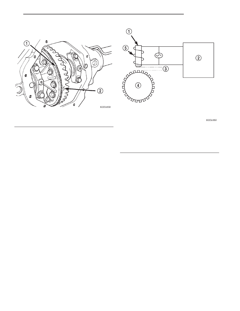
The WSS consists of a magnet surrounded by

windings from a single strand of wire. The sensor
sends a small AC signal to the CAB. This signal is
generated by magnetic induction. The magnetic
induction is created when a toothed sensor ring
(exciter ring or tone wheel) passes the stationary
magnetic WSS.

When the ring gear is rotated, the exciter ring

passes the tip of the WSS. As the exciter ring tooth
approaches the tip of the WSS, the magnetic lines of
force expand, causing the magnetic field to cut across
the sensor’s windings. This, in turn causes current to
flow through the WSS circuit (Fig. 4) in one direc-
tion. When the exciter ring tooth moves away from
the sensor tip, the magnetic lines of force collapse
cutting the winding in the opposite direction. This
causes the current to flow in the opposite direction.
Every time a tooth of the exciter ring passes the tip
of the WSS, an AC signal is generated. Each AC sig-
nal (positive to negative signal or sinewave) is inter-
preted by the CAB. It then compares the frequency of
the sinewave to a time value to calculate vehicle
speed. The CAB continues to monitor the frequency
to determine a deceleration rate that would indicate
a possible wheel-locking tendency.

The signal strength of any magnetic induction sen-

sor is directly affected by:

• Magnetic field strength; the stronger the mag-

netic field, the stronger the signal

• Number of windings in the sensor; more wind-

ings provide a stronger signal

• Exciter ring speed; the faster the exciter ring

rotates, the stronger the signal will be

• Distance between the exciter ring teeth and

WSS; the closer the WSS is to the exciter ring, the
stronger the signal will be

The rear WSS is not adjustable. A clearance speci-

fication has been established for manufacturing toler-
ances.

If

the

clearance

is

not

within

these

specifications, then either the WSS or other compo-
nents may be damaged. The clearance between the
WSS and the exciter ring is 0.005 – 0.050 in.

The assembly plant performs a “Rolls Test” on

every vehicle that leaves the assembly plant. One of
the test performed is a test of the WSS. To properly
test the sensor, the assembly plant connects test
equipment to the Data Link Connector (DLC). This
connector is located to the right of the steering col-
umn and attached to the lower portion of the instru-
ment panel (Fig. 5). The rolls test terminal is spliced
to the WSS circuit. The vehicle is then driven on a
set of rollers and the WSS output is monitored for
proper operation.

BRAKE WARNING LAMPS

DESCRIPTION

The red brake warning lamp and amber ABS

warning lamp are located in the instrument cluster.
The red brake warning lamp is used to alert the
driver of a hydraulic fault or that the parking brake
is applied. For the RWAL system, the red brake

Fig. 3 Exciter Ring Location

1 – EXCITER RING
2 – RING GEAR

Fig. 4 Operation of the Wheel Speed Sensor

1 – MAGNETIC CORE
2 – CAB
3 – AIR GAP
4 – EXCITER RING
5 – COIL

DN

BRAKES

5 - 35

DESCRIPTION AND OPERATION (Continued)

warning lamp also is used to alerts the driver of a
problem with the RWAL system.

OPERATION

The red brake warning lamp illuminates when a

message is sent over the bus to the cluster to illumi-
nate the bulb. A ground for the bulb is provided
when:

• The parking brake is applied and the park brake

switch is actuated.

• A hydraulic fault has occurred and the pressure

differential switch is actuated.

• A RWAL fault has occurred.
The amber ABS warning lamp is used to alert the

driver of an RWAL problem and identify DTCs stored
in the CABs memory.

BRAKE LAMP SWITCH

DESCRIPTION

The plunger type brake lamp switch is mounted on

a bracket attached to the brake pedal support.

CAUTION: The switch can only be adjusted during
initial installation. If the switch is not adjusted prop-
erly a new switch must be installed.

OPERATION

The primary function of the switch is to turn on

the brake lamps during braking. The switch is also
used to send signals to components that must know
when the brakes are applied, such as the Powertrain
Control Module (PCM), which uses the signal to can-
cel speed control. The CAB uses the brake switch sig-
nal to monitor brake pedal application. When the
switch contacts open (brakes applied), the CAB

receives the brake applied signal. The CAB then
monitors the RWAL system to anticipate the need for
an RWAL stop.

DIAGNOSIS AND TESTING

REAR WHEEL ANTILOCK

Diagnosis of base brake conditions which are

mechanical in nature should be performed first. This
includes brake noise, lack of power assist, parking
brake, or vehicle vibration during normal braking.

The RWAL brake system performs several self-

tests every time the ignition switch is turned on and
the vehicle is driven. The CAB monitors the system
inputs and outputs circuits to verify the system is
operating properly. If the CAB senses a malfunction
in the system it will set a DTC into memory and trig-
ger the warning lamp.

NOTE: The MDS or DRB III scan tool is used to
diagnose the RWAL system. For test procedures
refer to the Chassis Diagnostic Manual. For addi-
tional information refer to the Antilock brake sec-
tion in Group 8W.

RWAL SERVICE PRECAUTIONS

The RWAL uses an electronic control module, the

CAB. This module is designed to withstand normal
current draws associated with vehicle operation.
Care must be taken to avoid overloading the CAB
circuits. In testing for open or short circuits, do
not ground or apply voltage to any of the cir-
cuits unless instructed to do so for a diagnostic
procedure. 
These circuits should only be tested
using a high impedance multi-meter or the DRB
tester as described in this section. Power should
never be removed or applied to any control module
with the ignition in the ON position. Before removing
or connecting battery cables, fuses, or connectors,
always turn the ignition to the OFF position.

CAUTION: Use only factory wiring harnesses. Do
not cut or splice wiring to the brake circuits. The
addition of after-market electrical equipment (car
phone, radar detector, citizen band radio, trailer
lighting, trailer brakes, ect.) on a vehicle equipped
with antilock brakes may affect the function of the
antilock brake system.

Fig. 5 Data Link Connector - Typical

1 – 16–WAY DATA LINK CONNECTOR

5 - 36

BRAKES

DN

DESCRIPTION AND OPERATION (Continued)

SERVICE PROCEDURES

REAR WHEEL ANTILOCK BRAKE BLEEDING

Use Mopar brake fluid, or an equivalent quality

fluid meeting SAE J1703-F and DOT 3 standards
only. Use fresh, clean fluid from a sealed container at
all times.

Do not pump the brake pedal at any time while

bleeding. Air in the system will be compressed into
small bubbles that are distributed throughout the
hydraulic system. This will make additional bleeding
operations necessary.

Do not allow the master cylinder to run out of fluid

during bleed operations. An empty cylinder will allow
additional air to be drawn into the system. Check the
cylinder fluid level frequently and add fluid as needed.

Bleed only one brake component at a time in the

following sequence:

• Master Cylinder

• Combination Valve

• Rear Antilock Valve

• Left Rear Wheel

• Right Rear Wheel

• Right Front Wheel

• Left Front Wheel

MANUAL BLEEDING

(1) Remove reservoir filler caps and fill reservoir.
(2) If calipers, or wheel cylinders were overhauled,

open all caliper and wheel cylinder bleed screws.
Then close each bleed screw as fluid starts to drip
from it. Top off master cylinder reservoir once more
before proceeding.

(3) Attach one end of bleed hose to bleed screw

and insert opposite end in glass container partially
filled with brake fluid (Fig. 6). Be sure end of bleed
hose is immersed in fluid.

(4) Open up bleeder, then have a helper press

down the brake pedal. Once the pedal is down close
the bleeder. Repeat bleeding until fluid stream is
clear and free of bubbles. Then move to the next
wheel.

PRESSURE BLEEDING

Follow the manufacturers instructions carefully

when using pressure equipment. Do not exceed the
tank manufacturers pressure recommendations. Gen-
erally, a tank pressure of 15-20 psi is sufficient for
bleeding.

Fill the bleeder tank with recommended fluid and

purge air from the tank lines before bleeding.

Do not pressure bleed without a proper master cyl-

inder adapter. The wrong adapter can lead to leak-
age, or drawing air back into the system. Use the
adapter provided with the equipment or Adapter
6921.

REMOVAL AND INSTALLATION

CONTROLLER

NOTE: If the CAB needs to be replaced, the rear
axle type and tire revolutions per mile must be pro-
gramed into the new CAB. For axle type refer to
Group 3 Differential and Driveline. For tire revolu-
tions per mile refer to Group 22 Tire and Wheels. To
program the CAB refer to the Chassis Diagnostic
Manual.

REMOVAL

(1) Push the CAB harness connector lock to

release the lock and remove the connector (Fig. 7)
from the controller.

(2) Remove the RWAL valve harness connector

from the controller.

(3) Remove the controller mounting screws and

remove the controller from the mounting bracket
(Fig. 7).

INSTALLATION

(1) Position the controller on the bracket.
(2) Install the mounting screws and tighten to 6

N·m (53 in. lbs).

(3) Install the RWAL valve harness connector into

the controller.

(4) Install the CAB harness connector into the con-

troller and push down on the connector lock.

Fig. 6 Bleed Hose Setup

1 – BLEED HOSE
2 – FLUID CONTAINER PARTIALLY FILLED WITH FLUID

DN

BRAKES

5 - 37

RWAL VALVE

REMOVAL

(1) Remove RWAL valve harness connector from

the RWAL controller.

(2) Remove the brake lines from the valve.
(3) Remove the valve mounting bolt (Fig. 8) and

remove the valve from the bracket.

INSTALLATION

(1) Position the valve on the bracket and install

the mounting bolt. Tighten the mounting bolt to
20-27 N·m (15-20 ft. lbs.).

(2) Install the brake lines and tighten to 19 N·m

(170 in. lbs.).

(3) Install the RWAL valve harness connector into

the RWAL controller.

(4) Bleed base brake system.

REAR WHEEL SPEED SENSOR

REMOVAL

(1) Raise vehicle on hoist.
(2) Remove brake line mounting nut and remove

the brake line from the sensor stud.

(3) Remove mounting stud from the sensor and

shield (Fig. 9).

(4) Remove sensor and shield from differential

housing.

(5) Disconnect sensor wire harness and remove

sensor.

INSTALLATION

(1) Connect harness to sensor. Be sure seal is

securely in place between sensor and wiring
connector.

(2) Install O-ring on sensor (if removed).
(3) Insert sensor in differential housing.
(4) Install sensor shield.
(5) Install the sensor mounting stud and tighten to

24 N·m (200 in. lbs.).

(6) Install the brake line on the sensor stud and

install the nut.

(7) Lower vehicle.

Fig. 7 RWAL Controller

1 – CAB CONNECTOR LOCK
2 – RWAL CONNECTOR
3 – MOUNTING SCREWS

Fig. 8 RWAL Valve

1 – RWAL VALVE
2 – MOUNTING BOLT
3 – BRAKE LINES

Fig. 9 Rear Speed Sensor Mounting

1 – DIFFERENTIAL HOUSING
2 – WHEEL SPEED SENSOR

5 - 38

BRAKES

DN

REMOVAL AND INSTALLATION (Continued)


Content   ..  245  246  247  248   ..