Dodge Durango (DN). Manual - part 43
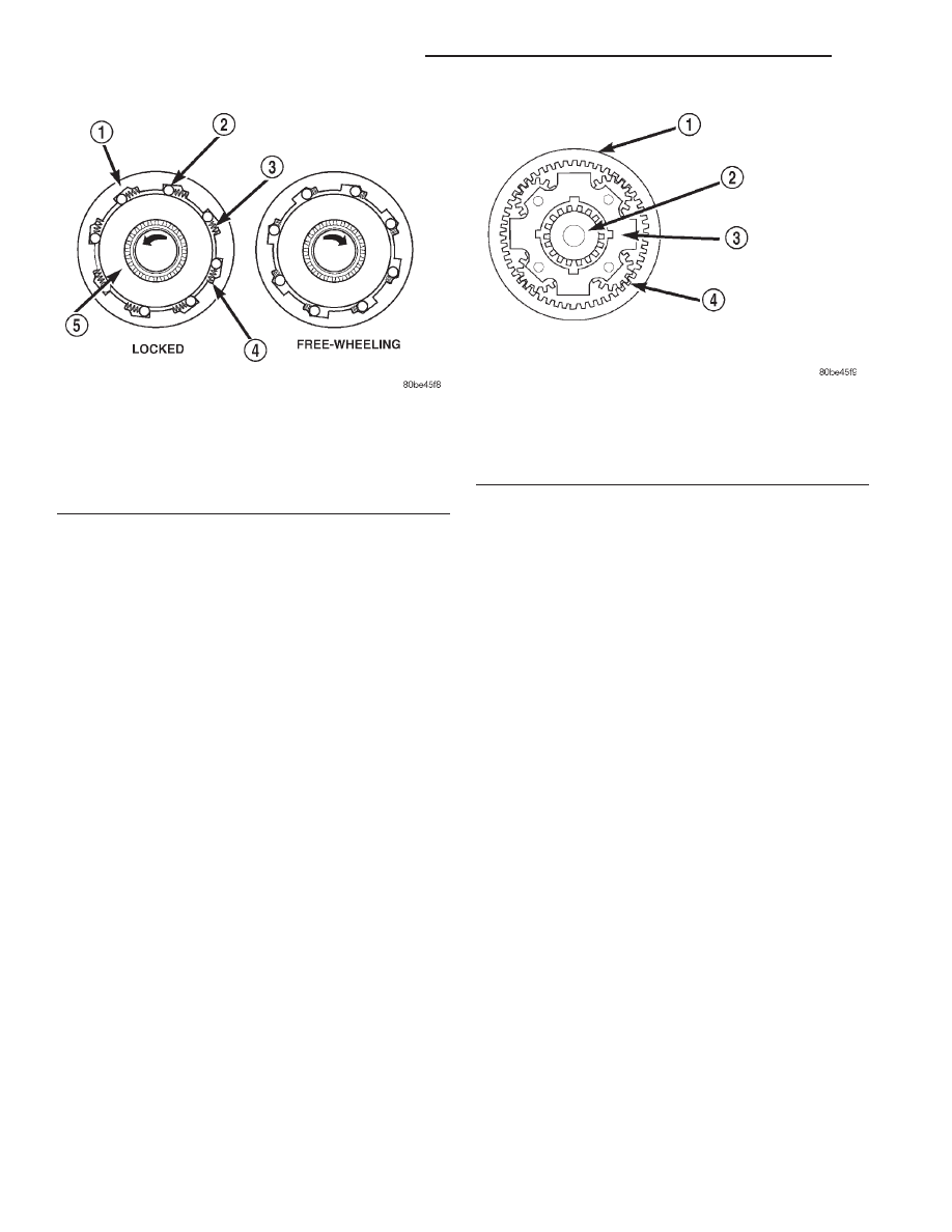
rotate counterclockwise, the action causes the rollers
to roll in the same direction as the race, aided by the
pushing of the springs. As the rollers try to move in
the same direction as the inner race, they are
wedged between the inner and outer races due to the
design of the cam. In this condition, the clutch is
locked and acts as one unit.
PLANETARY GEARSET
DESCRIPTION
The planetary gearsets (Fig. 58) are designated as
the front, rear, and overdrive planetary gear assem-
blies and located in such order. A simple planetary
gearset consists of three main members:
• The sun gear which is at the center of the sys-
tem.
• The planet carrier with planet pinion gears
which are free to rotate on their own shafts and are
in mesh with the sun gear.
• The annulus gear, which rotates around and is
in mesh with the planet pinion gears.
NOTE: The number of pinion gears does not affect
the gear ratio, only the duty rating.
OPERATION
With any given planetary gearset, several condi-
tions must be met for power to be able to flow:
• One member must be held.
• Another member must be driven or used as an
input.
• The third member may be used as an output for
power flow.
• For direct drive to occur, two gear members in
the front planetary gearset must be driven.
NOTE: Gear ratios are dependent on the number of
teeth on the annulus and sun gears.
BANDS
DESCRIPTION
KICKDOWN (FRONT) BAND
The kickdown, or “front”, band (Fig. 59) holds the
common sun gear of the planetary gear sets. The
front (kickdown) band is made of steel, and faced on
its inner circumference with a friction–type lining.
One end of the band is anchored to the transmission
case, and the other is acted on with a pushing force
by a servo piston. The front band is a single–wrap
design (the band does not completely encompass/
wrap the drum that it holds).
LOW/REVERSE (REAR) BAND
The low/reverse band, or “rear”, band (Fig. 60) is
similar in appearance and operation to the front
band.
OPERATION
KICKDOWN (FRONT) BAND
The kickdown band holds the common sun gear of
the planetary gear sets by applying and holding the
front clutch retainer, which is splined to the sun gear
driving shell, and in turn splined directly to the sun
Fig. 57 Overrunning Clutch
1 – OUTER RACE (CAM)
2 – ROLLER
3 – SPRING
4 – SPRING RETAINER
5 – INNER RACE (HUB)
Fig. 58 Planetary Gearset
1 – ANNULUS GEAR
2 – SUN GEAR
3 – PLANET CARRIER
4 – PLANET PINIONS (4)
21 - 38
42/44RE AUTOMATIC TRANSMISSION
DN
DESCRIPTION AND OPERATION (Continued)