Dodge Durango (DN). Manual - part 6


  Index      Dodge     Dodge Durango (DN) - service repair manual 2000 year


Search            


Content   ..  4  5  6  7   ..


Dodge Durango (DN). Manual - part 6


FRONT BUMPER INNER BRACKET

REMOVAL

(1) Remove bolts attaching top of bumper to

bumper bracket.

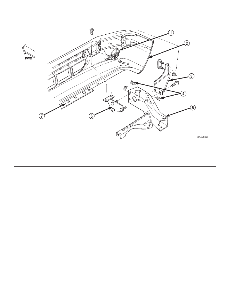
(2) Remove nuts attaching inner bumper bracket

to frame (Fig. 1).

(3) Using a shallow socket and extension or equiv-

alent, tap with a hammer to drive inner bumper
bracket studs out of frame.

(4) Separate inner bumper bracket from frame.

INSTALLATION

(1) Position

inner

bumper

bracket

studs

into

frame.

(2) Install nuts attaching inner bumper bracket to

frame. Tighten nuts to 94 N·m (70 ft. lbs.) torque.

(3) Install bolts attaching top of bumper to bumper

bracket.

FRONT BUMPER FASCIA

REMOVAL

(1) Remove the front bumper.

(2) Remove the bolts attaching the fascia to the

bumper.

(3) Separate fascia from bumper.

INSTALLATION

(1) Position fascia on bumper.
(2) Install the bolts attaching the fascia to the

bumper.

(3) Install the front bumper.

REAR BUMPER

REMOVAL

(1) Remove trailer hitch, if equipped.
(2) Raise and support the rear of the vehicle.
(3) Support the bumper.
(4) Remove rivets at each side rear wheel well.
(5) Disconnect license plate lamp wiring harness.
(6) Remove nuts attaching bumper support brack-

ets to rear rails and crossmember (Fig. 2).

(7) Remove the bumper/fascia from the vehicle.

INSTALLATION

(1) Position the bumper/fascia on the vehicle.

Fig. 1 Front Bumper

1 – FOG LAMP
2 – FRONT BUMPER
3 – OUTER BUMPER BRACKET
4 – U-NUT

5 – FRAME
6 – INNER BUMPER BRACKET
7 – FASCIA BRACKET

13 - 2

FRAME AND BUMPERS

DN

REMOVAL AND INSTALLATION (Continued)

(2) Install nuts attaching bumper support brackets

to crossmember and rear rails (Fig. 2).

(3) Check

gaps

and

fit. Adjust

as

necessary.

Tighten nuts to 54 N·m (40 ft. lbs.) torque.

(4) Connect license plate lamp wiring harness.
(5) If equipped, install the trailer hitch.

REAR BUMPER FASCIA

REMOVAL

(1) Remove rivets at each side rear wheel well.

NOTE: Removing the step pad will damage the step
pad retainers, verify availability of step pad from
parts supplier.

(2) Using a trim stick, carefully pry step pad from

fascia.

(3) Disconnect license plate lamp connector.
(4) Remove upper push pin from the bumper fascia

(Fig. 3).

(5) Remove the lower push pins from the bumper

fascia.

Fig. 2 Rear Bumper

1 – BUMPER BEAM
2 – PUSH—PIN
3 – STEP PAD
4 – PUSH—PIN
5 – PUSH—PIN
6 – FASCIA

7 – SHIELD
8 – BLIND RIVET
9 – FASCIA BRACKET
10 – BUMPER BRACKET
11 – FRAME

DN

FRAME AND BUMPERS

13 - 3

REMOVAL AND INSTALLATION (Continued)

(6) Remove the bumper fascia from the bumper

(Fig. 2).

INSTALLATION

(1) Position the bumper fascia on the bumper (Fig.

2).

(2) Install upper push pin.
(3) Align all holes and install the lower push pins.
(4) Position step pad on fascia and press into

place.

(5) Connect license plate lamp connector.
(6) Align fascia bracket, wheel house liner shield

and fascia holes and install rivets.

Fig. 3 Rear Fascia

1 – LICENSE PLATE LAMP CONNECTOR
2 – FASCIA
3 – PUSH PIN
4 – RIVET
5 – PUSH PIN
6 – RIVET

13 - 4

FRAME AND BUMPERS

DN

REMOVAL AND INSTALLATION (Continued)

FRAME

TABLE OF CONTENTS

page

page

DESCRIPTION AND OPERATION

FRAME . . . . . . . . . . . . . . . . . . . . . . . . . . . . . . . . . 5

SERVICE PROCEDURES

FRAME SERVICE . . . . . . . . . . . . . . . . . . . . . . . . . 5

REMOVAL AND INSTALLATION

FRONT AXLE SKID PLATE. . . . . . . . . . . . . . . . . . . 6
TRANSFER CASE SKID PLATE . . . . . . . . . . . . . . . 7

FUEL TANK SKID PLATE—4WD VEHICLES . . . . . . 7
SPARE TIRE WINCH . . . . . . . . . . . . . . . . . . . . . . . 7
TRAILER HITCH . . . . . . . . . . . . . . . . . . . . . . . . . . 8

SPECIFICATIONS

FRAME DIMENSIONS . . . . . . . . . . . . . . . . . . . . . . 8
TORQUE SPECIFICATIONS . . . . . . . . . . . . . . . . . 10

DESCRIPTION AND OPERATION

FRAME

DESCRIPTION

The DN uses a three section frame design. The

ends of the center section are swaged to fit into the
front and rear sections. The front, center, and rear
sections are welded together. The frame is serviced
as a complete unit only.

OPERATION

The frame is designed to absorb and dissipate flex-

ing and twisting due to acceleration, braking, corner-
ing and road surface variances without bending when
subjected to normal driving conditions. The frame is
the mounting platform for the following systems and
components:

• Engine, transmission, and transfer case.

• Exhaust system and heat shields.

• Front and rear bumper systems.

• Front and rear suspension systems.

• Front end sheet metal and radiator closure

panel.

• Fuel cell and fuel line tubing.

• Parking brake.

• Steering gear and linkage.

• Skid plate.

• Spare tire winch.

• Trailer hitch.

• Vehicle body.

SERVICE PROCEDURES

FRAME SERVICE

SAFETY PRECAUTIONS AND WARNINGS

WARNING: USE EYE PROTECTION WHEN GRIND-
ING OR WELDING METAL, SERIOUS EYE INJURY

CAN RESULT. BEFORE PROCEEDING WITH FRAME
REPAIR INVOLVING GRINDING OR WELDING, VER-
IFY THAT VEHICLE FUEL SYSTEM IS NOT LEAKING
OR IN CONTACT WITH REPAIR AREA, PERSONAL
INJURY CAN RESULT. DO NOT ALLOW OPEN
FLAME TO CONTACT PLASTIC BODY PANELS.
FIRE

OR

EXPLOSION

CAN

RESULT.

WHEN

WELDED FRAME COMPONENTS ARE REPLACED,
100% PENETRATION WELD MUST BE ACHIEVED
DURING

INSTALLATION.

IF

NOT,

DANGEROUS

OPERATING CONDITIONS CAN RESULT. STAND
CLEAR OF CABLES OR CHAINS ON PULLING
EQUIPMENT

DURING

FRAME

STRAIGHTENING

OPERATIONS, PERSONAL INJURY CAN RESULT.
DO NOT VENTURE UNDER A HOISTED VEHICLE
THAT IS NOT SUPPORTED ON SAFETY STANDS,
PERSONAL INJURY CAN RESULT.

CAUTION: Do not reuse damaged fasteners, quality
of repair would be suspect. Do not drill holes in top
or bottom frame rail flanges, frame rail failure can
result. Do Not use softer than Grade 5 bolts to
replace production fasteners, loosening or failure
can result. When using heat to straighten frame
components do not exceed 566°C (1050°F), metal
fatigue can result. Welding the joints around riveted
cross members and frame side rails can weaken
frame.

FRAME STRAIGHTENING

When necessary, a conventional frame that is bent

or twisted can be straightened by application of heat.
The temperature must not exceed 566°C (1050°F).
The metal will have a dull red glow at the desired
temperature.

Excessive

heat

will

decrease

the

strength of the metal and result in a weakened
frame.

A straightening repair process should be limited to

frame members that are not severely damaged. The

DN

FRAME AND BUMPERS

13 - 5


Content   ..  4  5  6  7   ..