Index Dodge Chrysler Le Baron, Dodge Dynasty, Plymouth Acclaim - service repair manual 1993 year
Search
Content .. 91 92 93 94 ..
Chrysler Le Baron, Dodge Dynasty, Plymouth Acclaim. Manual - part 93
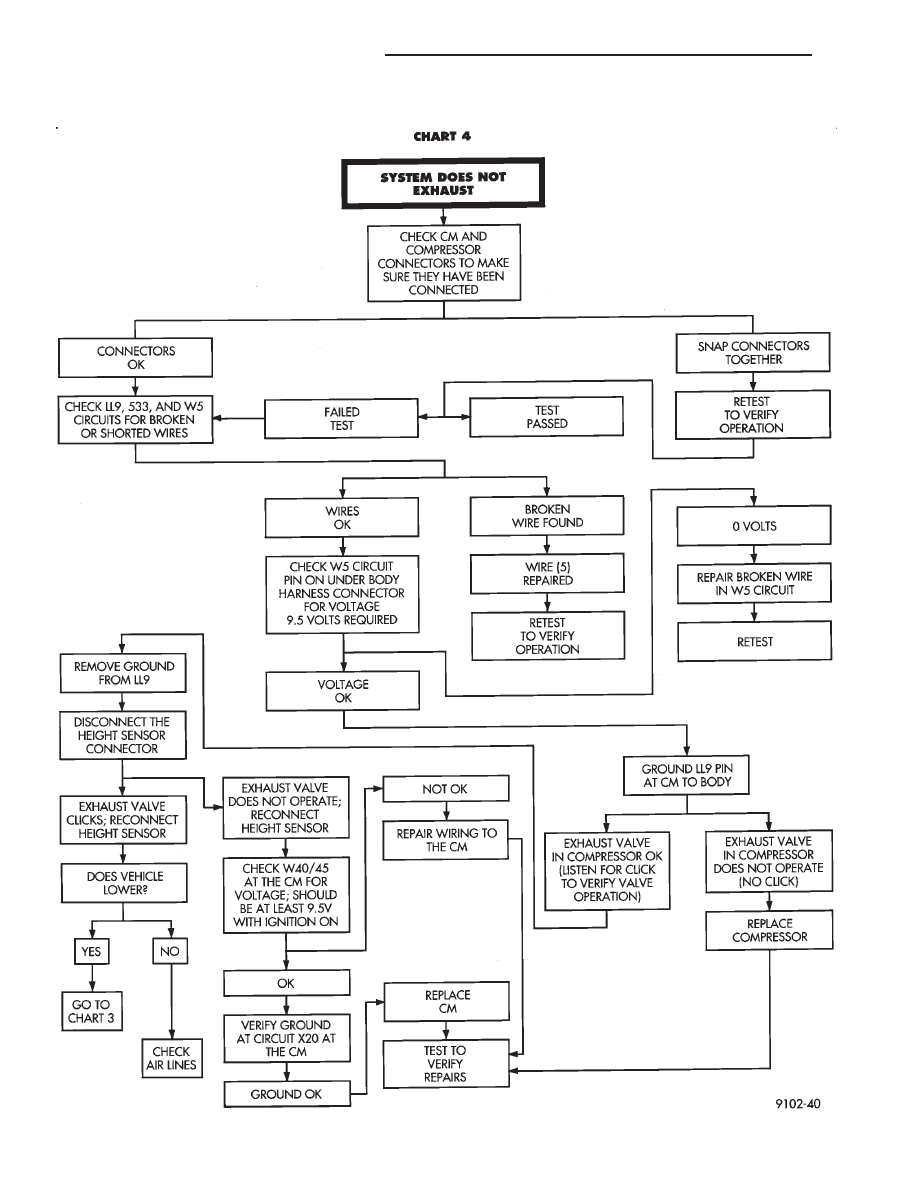
AUTOMATIC AIR LOAD LEVELING DIAGNOSTICS
2 - 70
SUSPENSION AND DRIVESHAFTS
Ä