Daewoo Korando. Manual - part 353
REMOTE KEYLESS ENTRY AND ANTI-THEFT SYSTEM 9T-5
MAINTENANCE AND REPAIR
ON-VEHICLE SERVICE
REKES
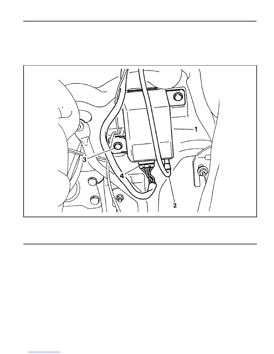
1 REKES Receiver
2 Antenna
3 Bolt
4 Wiring Connector (6P)
|
|
|
REMOTE KEYLESS ENTRY AND ANTI-THEFT SYSTEM 9T-5 MAINTENANCE AND REPAIR ON-VEHICLE SERVICE REKES 1 REKES Receiver 3 Bolt |