Daewoo Korando. Manual - part 36


  Index      Daewoo     Daewoo Korando - service repair manual


Search            


Content   ..  34  35  36  37   ..


Daewoo Korando. Manual - part 36


1B1-80  M162 ENGINE MECHANICAL

Tools Required

104 589 01 01 00  Spanner

Removal & Installation Procedure

1. Remove the chain tensioner (1).

2. Turn the exhaust camshaft to the camshaft rotating direction

using the wrench (4) and loosen the timing chain at upper
guide rail (2).

3. Pull out the upper guide rail pin from the guide rail (2).

4. Turn the exhaust camshaft to the opposite direction of

rotation using the wrench (4, special tool : 104 589 01 01
00).

5. Check for damages at the upper sliding rail and replace it if

necessary. Install the upper guide rail pin.

6. Install the chain tensioner.

Installation Notice

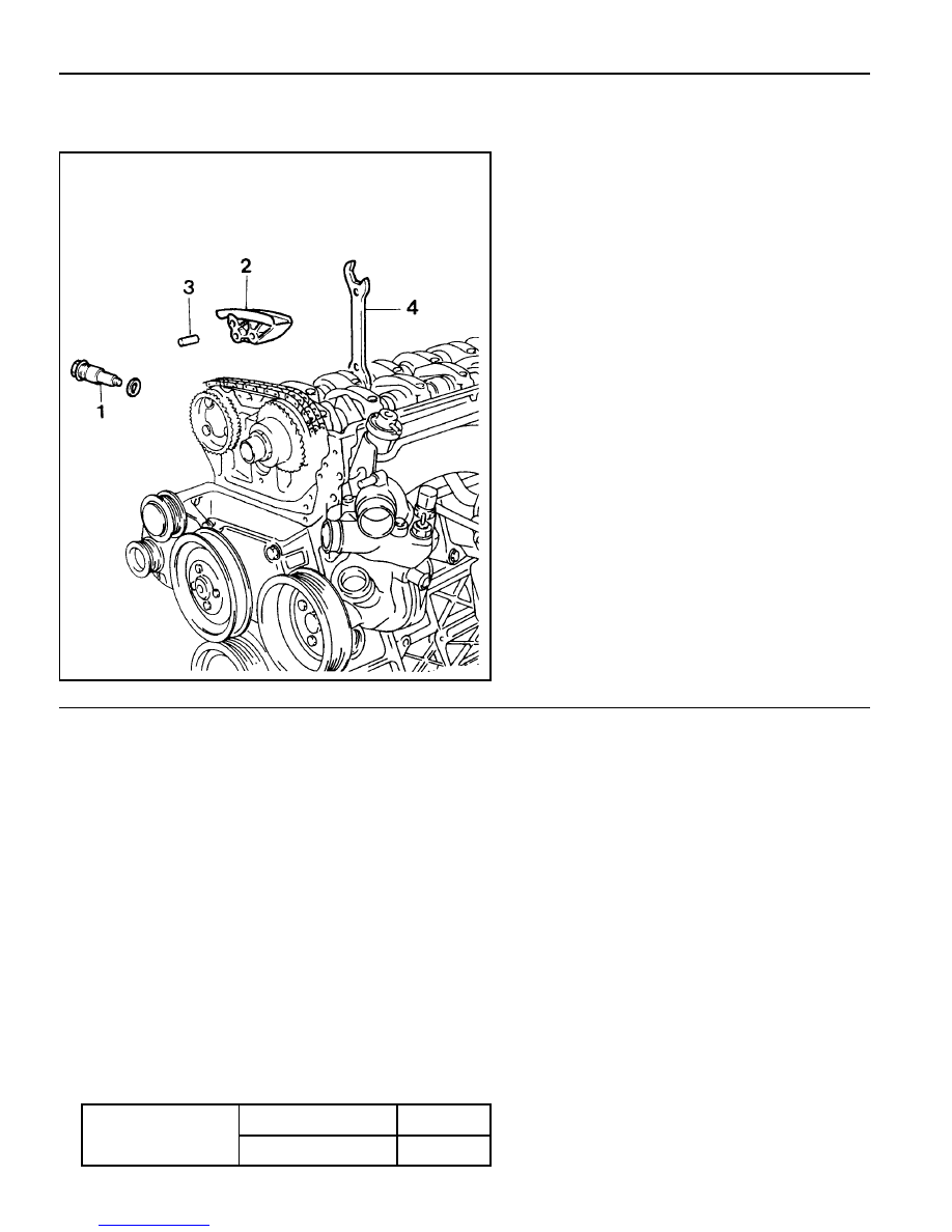
CYLINDER HEAD GUIDE RAIL

Preceding Work : Removal of cylinder head cover

1 Chain Tensioner
2 Upper Guide Rail
3 Upper Guide Rail Pin
4 Wrench (Special Tool)

Tightening Torque

Screw Plug

40 Nm

Tensioner Assembly

72 - 88 Nm

M162 ENGINE MECHANICAL  1B1-81

CRANKCASE GUIDE RAIL

Preceding Work : Removal of timing gear case cover

1 Guide Rail
2 Plastic Guide
3 Guide Rail Pin
4 Tensioning Rail

Removal & Installation Procedure

1. Put the assembly mark at the camshaft sprocket and the

timing chain with the paint (arrow).

2. Remove the exhaust camshaft sprocket.

3. Remove the guide rail (1) from the guide rail pin (3).

Notice

l

Replace the plastic guide (2) if damaged.

l

Connect the plastic guide (2) and the guide rail (1) by

aligning them accurately when installing.

4. Installation should follow the removal procedure in the

reverse order.

5. Check the camshaft timing position.

1B1-82  M162 ENGINE MECHANICAL

CRANKSHAFT SPROCKET

Preceding Work : Removal of oil pan

Removal of tensioning rail
Removal of crank case guide rail

6 Bolt (M8 x 20, 1 piece) / Washer .......... 29-35 Nm
7 Oil Pump Sprocket
8 Oil Pump
9 Oil Pump Roller Chain

10 Timing Chain

1 Oil Pump Chain Tensioner
2 Oil Pump Chain Bushing
3 Oil Pump Chain Spring
4 Crankshaft Sprocket
5 Key

M162 ENGINE MECHANICAL  1B1-83

Tools Required

615 589 01 33 00  Puller

Removal & Installation Procedure

1. Put the assembly mark at the crankshaft sprocket (4) and

the timing chain (10) with the paint (arrow).

Installation Notice

Align the assembly marks on cranshaft sprocket and timing
chain. Also, align the assembly marks on camshaft sprocket
and timing chain when installing.

2. Unscrew the bolt (6) and remove the oil pump sprocket (7)

from the oil pump.

Installation Notice

Puller (04) 615 589 01 33 00

3. Remove the oil pump roller chain (9).

4. Remove the oil pump chain tensioner (1), oil pump chain

bushing (2), and the oil pump chain spring (3).

5. Remove the crankshaft sprocket (4) using the puller (04,

special tool).

Notice

l

Make sure not to lose the crankshaft pulley key(5) when

removing.

l

Install the crankshaft sprocket(4) after warming it up.

6. Installation should follow the removal procedure in the

reverse order.

Tightening  Torque

29 - 35 Nm


Content   ..  34  35  36  37   ..