Daewoo Korando. Manual - part 34


  Index      Daewoo     Daewoo Korando - service repair manual


Search            


Content   ..  32  33  34  35   ..


Daewoo Korando. Manual - part 34


1B1-72  M162 ENGINE MECHANICAL

Installation Procedure

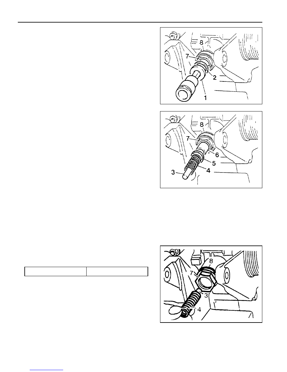
1. Connect the thrust pin (6) and the snap ring (5) to the chain

tensioner housing (7).

Notice

When connecting the thrust pin, push in the thrust pin far
enough so that it doesn’t protrude at the chain tensioner
housing.

4. Carefully unscrew the screw plug (1), and remove the seal

(2).

Notice

l

For the removal of screw plug, be careful that it can be

jumped out due to the force of compression spring.

l

Remove the screw plug only when the seal and

compression spring are damaged.

5. Carefully remove the filler pin (3), compression spring (4),

snap ring (5), and the thrust pin (6).

6. Remove the chain tensioner housing (7) and the seal (8).

3. Insert the compression spring (4) with the filler pin (3) into

chain tensioner housing.

2. Install the chain tensioner housing (7), thrust pin (6), snap

ring (5), and the seal (8).

Installation Notice

Tightening  Torque

35 - 40 Nm

M162 ENGINE MECHANICAL  1B1-73

4. Lightly apply the grease to the seal (2) and install the screw

plug (1).

Installation Notice

Sectional View

1 Screw Plug
2 Ball (Nonreturn Valve)
3 Compression Spring
4 Ball Guide
5 Seal (Aluminum)
6 Filler Pin
7 Compression Spring
8 Snap Ring
9 Thrust Pin

10 Ball (Nonreturn Valve)

11 Compression Spring

12 Thrust Piece

13 Chain Tensioner Housing
14 Seal
15 Timing Gear Case Cover
16 Cylinder Head
17 Bolt / Washer
18 Tensioning Rail
19 Cylinder Head Gasket
20 Timing Chain
21 Tensioning Rail Base (Sliding Surface)

A Oil Supply Hole
B Chain Tensioner Oil Storage Hole

5. Check for leaks by operating the engine.

Tightening Torque

40 Nm

1B1-74  M162 ENGINE MECHANICAL

TIMING CHAIN

Preceding Work : Removal of cylinder head cover

Removal of spark plug

1 Pin
2 New Timing Chain
3 Timing Chain (Used)
4 Wedge

5 Link
6 Center Plate
7 Outer Plate

M162 ENGINE MECHANICAL  1B1-75

Tools Required

000 589 58 43 00 Chain Assembly

103 589 01 63 00 Rivet Set

001 589 72 21 00 Torque Wrench

Replacement Procedure

1. Position the No.1 cylinder to TDC (OT).

4. Mount the wedges to both sides of the camshaft sprocket

as shown in the figure.

2. Insert the 

f

4mm pin to the intake and exhaust camshaft

flange not to rotate camshaft.

3. Remove the chain tensioner.

5. Cover the chain housing with a clean cloth, and grind off

the timing chain pin from the intake camshaft sprocket with
the grinder.


Content   ..  32  33  34  35   ..