DAF CF65, CF75, CF85 Series . Manual - part 964
©
200423
4-1
Removal and installation
STEERING BOX
ΧΦ65/75/85 series
7
3
4. REMOVAL AND INSTALLATION
4.1 REMOVAL AND INSTALLATION, ENTIRE STEERING BOX
If the vehicle has been involved in a
collision in which the steering box or
other components of the steering
gear have (possibly) been damaged,
the steering box should always be
sent to DAF for inspection or be
replaced. This instruction even
applies if no external damage is
visible. In the collision, the steering
box may have sustained internal
damage, causing it to be unreliable.
Removing the entire steering box
1.
Clean the steering box and the surrounding
area.
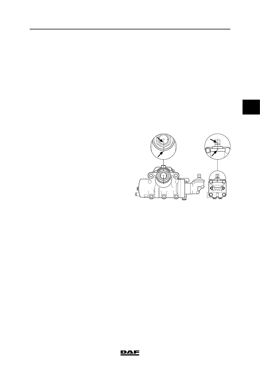
2.
Place the steering gear in the central
position. This can be checked using the
markings on the steering box.
3.
With an EMAS-controlled trailing axle,
remove the connector from the angle sensor.
4.
Remove the steering oil pipes from the
steering box. Collect the steering oil flowing
out and plug the openings of the pipes and at
the steering box, to prevent dirt entering.
Note:
If the pipe connections might accidentally be
switched, they should be marked.
5.
Remove the steering rod from the pitman
arm.
Note:
When a steering rod has been removed, the
input shaft must not be rotated more than
1.5 turns (counting from the central position)
because otherwise the setting of the wheel
deflection limiting valves will be changed.
6.
If present, detach the wiring harness and/or
other pipes from the steering bracket.
7.
Remove the steering shaft from the steering
box input shaft.
Note: The steering box weighs
approx. 35 kg. The steering box
should be supported securely and
responsibly, or safely suspended in
a hoist.
}
S7 00 024
}