DAF CF65, CF75, CF85 Series . Manual - part 924


  Index      DAF     DAF CF65, CF75, CF85 Series - service repair manual


Search            


Content   ..  922  923  924  925   ..


DAF CF65, CF75, CF85 Series . Manual - part 924


©

 200423

3-45

Removal and installation

BRAKE SYSTEM AND COMPONENTS

ΧΦ65/75/85 series

6

5

3.24 REMOVING AND INSTALLING BELLOWS WITH 

KNORR SN7000 BRAKE CALLIPER THRUST PIECE

Removing bellows with SN7000 brake calliper 
thrust piece
1.

Using the hexagonal adjusting bolt, unscrew 
the thrust pieces as far as is necessary to 
gain access to the bellows.

Note:
Unscrew the thrust pieces a maximum of 
30 mm. Do not screw them completely out of 
the brake calliper, as the brake calliper 
assembly would then have to be replaced.

Note:
Never turn the hexagonal adjusting bolt 
without using an adapter. The adapter 
is a torque safety and will break off when the 
torque is too high. Without the use of an 
adapter the mechanics in the brake calliper 
may become damaged when the torque 
is too high, so that replacement of the brake 
calliper may be necessary.
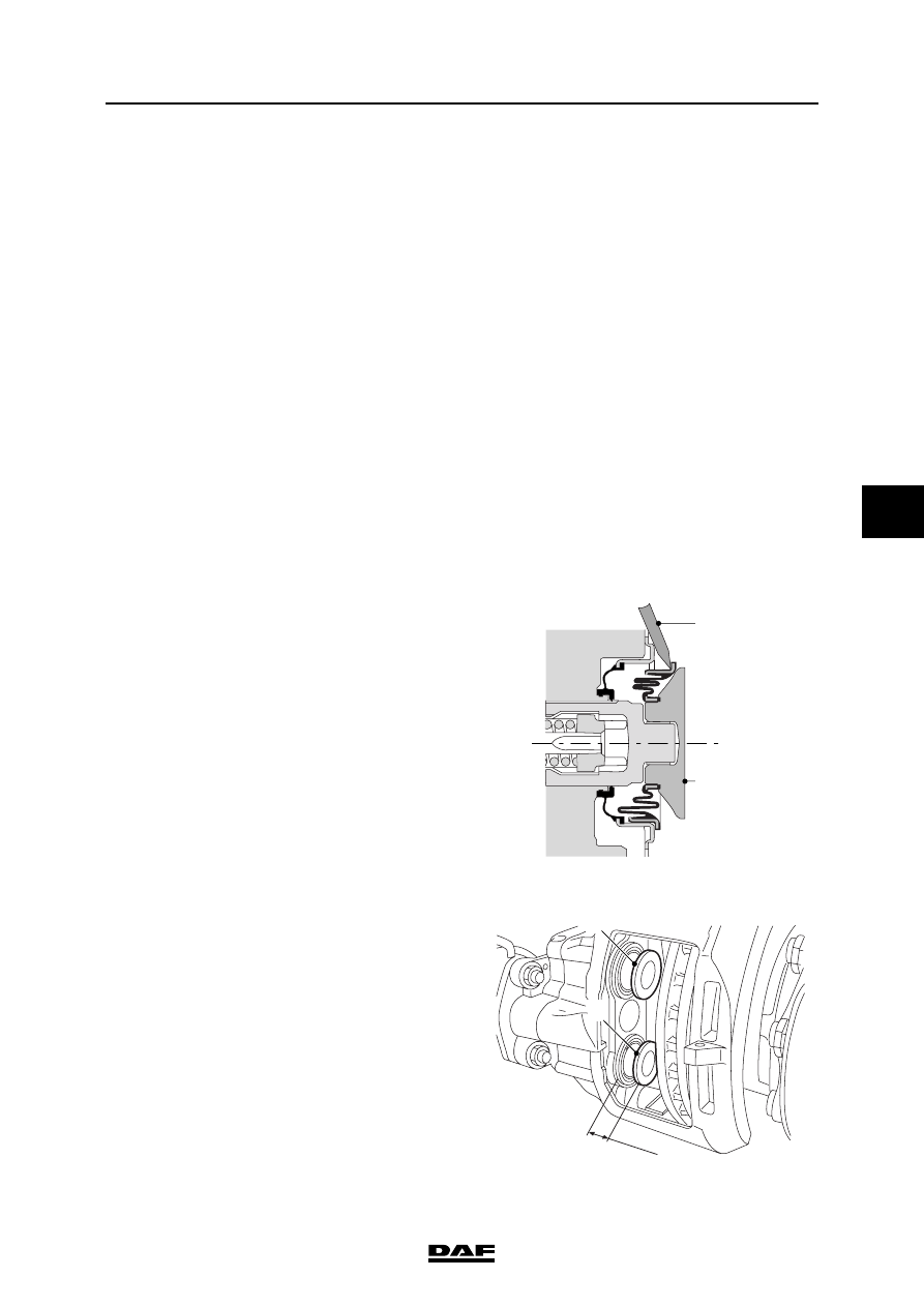
2.

Using a screwdriver (1), ease the bellows 
behind the thrust piece (2) out of the brake 
calliper.

30 mm

2

2

1

2

R600713

BRAKE SYSTEM AND COMPONENTS

3-46

©

 200423

Removal and installation

5

ΧΦ65/75/85 series

6

Note:
Do not insert the screwdriver (3) too deeply 
into the brake calliper. This could damage 
the seat (6) of the inner seal (5) of the thrust 
pieces. These cannot be replaced and the 
brake calliper would then have to be 
replaced.

3.

Press the thrust pieces (2) off the adjusters 
with the disassembly fork (3), special tool set 
(DAF no. 1329495).

4.

Remove the bearing bushes (4) from the 
thrust pieces.

Note:
If the bellows of the thrust piece is replaced, 
the inner seal must also always be replaced.

5.

Place a brake pad in the brake calliper 
on the outside so that the adjusters cannot 
be screwed out of the brake calliper at the 
next check. Place a 70-mm-thick spacer 
(self-made) if the brake calliper has been 
removed from the axle.

6.

Screw the adjuster about 30 mm out of the 
brake calliper and check the thread of the 
adjuster for dirt, corrosion and damage.

7.

Screw the adjuster all the way back into the 
brake calliper.

8.

Using a screwdriver, ease the inner seal out 
of the brake calliper.

Fitting bellows with SN7000 brake calliper 
thrust piece
1.

Clean the adjuster.

R600714

2

3

3

5

6

4

©

 200423

3-47

Removal and installation

BRAKE SYSTEM AND COMPONENTS

ΧΦ65/75/85 series

6

5

2.

Fit the new inner seal (1) on the adjuster.

3.

Assemble the press from (3) the special tool 
set (DAF no. 1329495), by means of T3 and 
T9. If the brake calliper has been removed, 
T4 must be screwed in between.

4.

Using the assembled press (3), push the 
inner seal (1) onto the adjuster (2).

5.

Check that the inner seal is seated correctly 
by rotating the adjuster 4 or 5 turns out of the 
brake calliper using the hexagonal adjusting 
bolt. The inner seal must not turn with it.

6.

Grease the screw thread of the adjusters. 
See "Technical data".

7.

Screw the adjusters back into the brake 
calliper.

R600715

3

3

2

1

T9

R600788

T4

T3

T9

T3

BRAKE SYSTEM AND COMPONENTS

3-48

©

 200423

Removal and installation

5

ΧΦ65/75/85 series

6

8.

Fit new bearing bushes (4) on the adjusters.

9.

Fit the thrust pieces and bellows (5) on the 
adjusters.

10. Assemble the press (6) from the special 

tool set (DAF no. 1329495), by means of T1, 
T2 and T3. If the brake calliper has been 
removed, T4 (8) must be screwed in 
between.

R600716

6

5

4

6

R600718

8


Content   ..  922  923  924  925   ..