DAF CF65, CF75, CF85 Series . Manual - part 920


  Index      DAF     DAF CF65, CF75, CF85 Series - service repair manual


Search            


Content   ..  918  919  920  921   ..


DAF CF65, CF75, CF85 Series . Manual - part 920


©

 200423

3-29

Removal and installation

BRAKE SYSTEM AND COMPONENTS

ΧΦ65/75/85 series

6

5

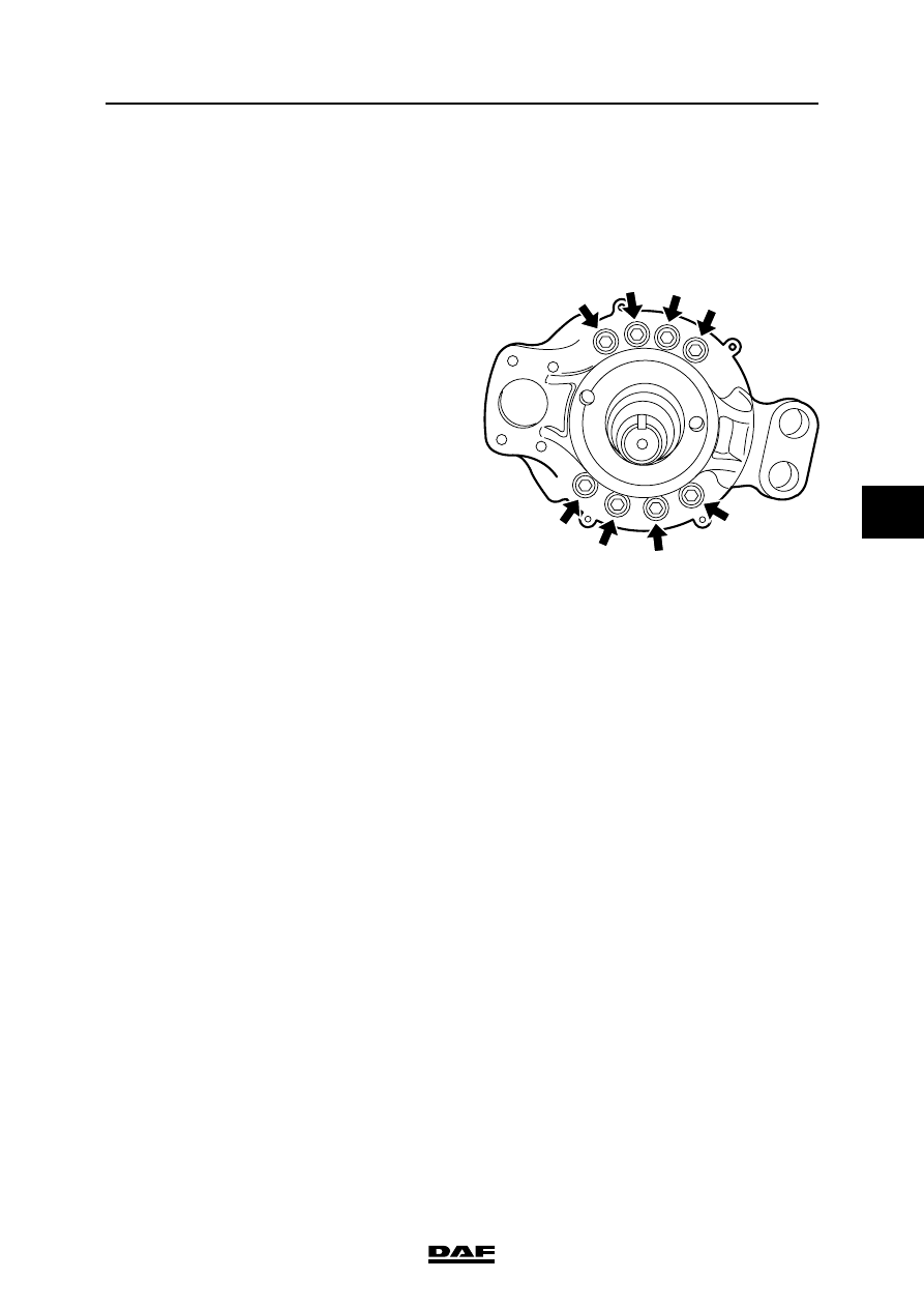
3.14 REMOVAL AND INSTALLATION, BRAKE BACK PLATE IN DRUM BRAKES

Removal, brake back plate
1.

Remove the brake drum.

2.

Remove the brake shoes.

3.

Remove the automatic slack adjuster.

4.

Remove the brake camshaft.

5.

Remove the hub.

6.

Remove the brake back plate.

Installation, brake back plate
1.

Clean the contact surfaces of the brake back 
plate and the spindle, and let these surfaces 
dry for approx. 20 minutes before installing 
the back plate. Thoroughly clean all other 
parts.

2.

Fit the back plate.

3.

Fit the hub.

4.

Fit the brake camshaft.

5.

Fit the brake shoes.

6.

Fit the brake drum.

7.

Fit the automatic slack adjuster.

R600156

BRAKE SYSTEM AND COMPONENTS

3-30

©

 200423

Removal and installation

5

ΧΦ65/75/85 series

6

3.15 REMOVAL AND INSTALLATION, BRAKE BACK PLATE IN DISC BRAKES

Removal, brake back plate
1.

Remove the brake calliper.

2.

Remove the brake calliper carrier.

3.

Remove the hub (and brake disc).

4.

Remove the brake back plate.

Installation, brake back plate
1.

Clean the contact surfaces of the brake back 
plate and the spindle, and let these surfaces 
dry for approx. 20 minutes before installing 
the back plate. Thoroughly clean all other 
parts.

2.

Install the brake back plate and tighten the 
attachment bolts to the specified torque. 
See "Technical data".

3.

Install the hub (and brake disc).

4.

Fit the brake calliper carrier.

5.

Fit the brake calliper.

©

 200423

3-31

Removal and installation

BRAKE SYSTEM AND COMPONENTS

ΧΦ65/75/85 series

6

5

3.16 REMOVAL AND INSTALLATION, COMPRESSOR CYLINDER HEAD GASKET

Always replace the gaskets when 
carrying out repairs. 

Removing the cylinder head gasket
1.

Drain some of the coolant.

2.

Remove the suction line.

3.

Remove the delivery line.

4.

Remove the coolant connections.

5.

Remove the cylinder head bolts.

6.

Remove the cylinder head assembly.

Installing the cylinder head gasket
1.

Thoroughly clean all parts.

2.

Check whether there are any remnants on 
the piston in the compressor.

3.

Install the head gasket. Use studs if 
necessary to ease installation.

4.

Install the valve housing including the inlet 
plates and spring plates.

5.

Install the valve housing gasket and the 
cylinder head.

6.

Install the cylinder head bolts and tighten to 
the specified torque, starting from the centre 
bolt. See "Technical data".

7.

Install the suction line.

8.

Install the delivery line.

9.

Connect the coolant connections.

10. Fill the cooling system.

11. Check the operation of the compressor. 

See "Inspection and adjustment".

}

BRAKE SYSTEM AND COMPONENTS

3-32

©

 200423

Removal and installation

5

ΧΦ65/75/85 series

6

3.17 REMOVAL AND INSTALLATION, AIR DRYER FILTER ELEMENT

Note:
To be certain that the air dryer is functioning 
properly, the air reservoirs should regularly be 
checked for condensation.

If repeatedly more than the normal amount of 
water is drained off, the filter element will have 
to be replaced.

Under normal circumstances the element must 
be replaced at least once per year.


Content   ..  918  919  920  921   ..