DAF CF65, CF75, CF85 Series . Manual - part 918
©
200423
3-21
Removal and installation
BRAKE SYSTEM AND COMPONENTS
ΧΦ65/75/85 series
6
5
4.
Place the upper punch carefully in position
and gradually increase the force (this will
result in the upsetting of the rivet shank i.e.
filling the hole, and the formation of a collar
on the shank).
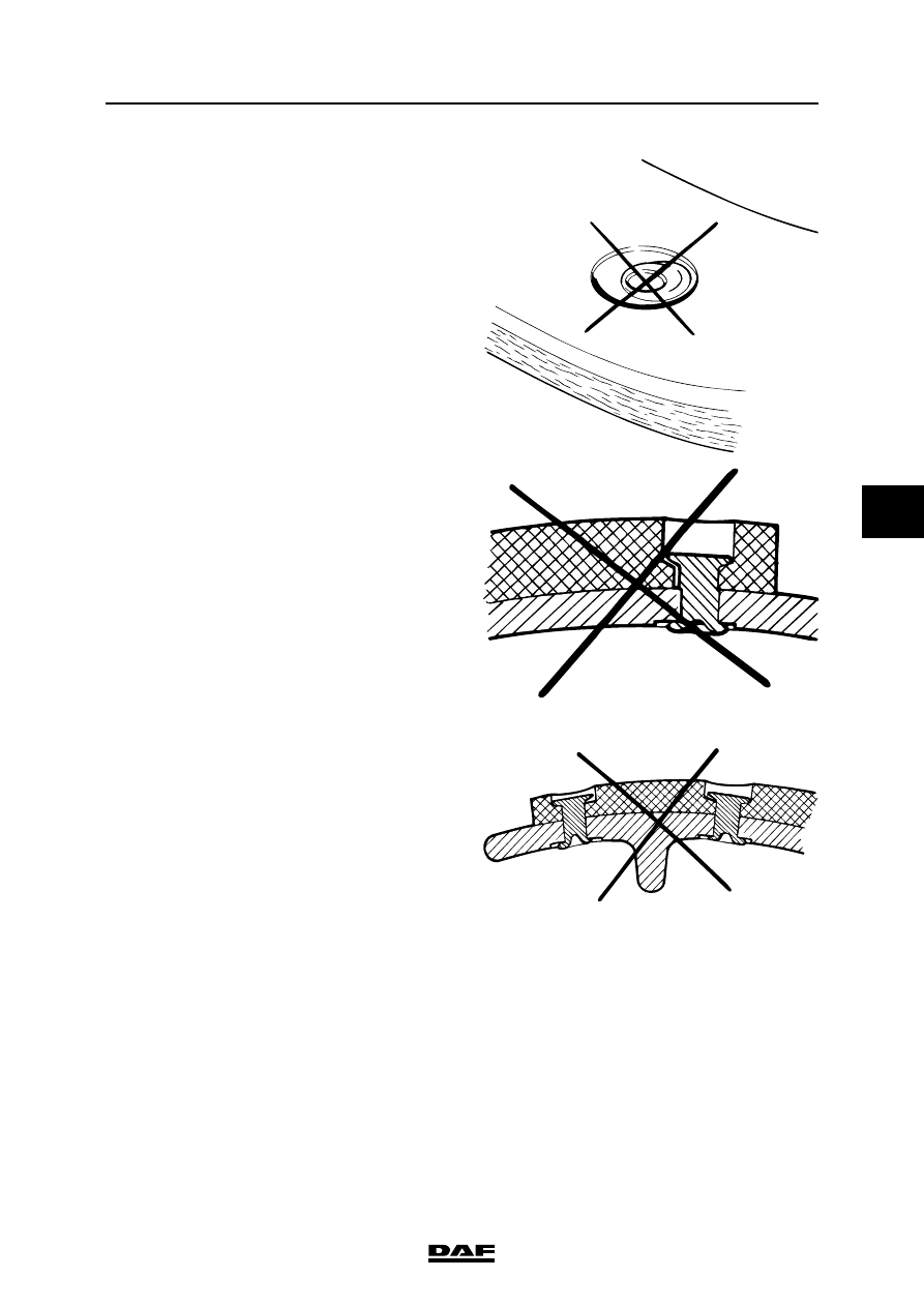
5.
Check the joints made for the following
points:
-
the collar formed on the shank must be
uniform all round and not flattened on
one side. If this is not the case:
-
the holes in the lining and brake shoe
are not in line.
-
the brake shoe was not held level during
the riveting process.
-
the rivets are wrong.
-
there must be no cracks in the collar
formed on the shank of the rivet.
If cracks are present, the clamping force
was too high.
-
the newly formed collar must abut the
brake shoe closely. Mark the halves
again if this is not the case.
-
the head of the rivet must not be forced
to one side in the lining. This can be
checked, for example, with the depth
measurement part of a calliper gauge
or visually by the asymmetrically formed
collar on the shank. If the head of the
rivet has been forced to one side in the
lining, the holes in the lining and the
brake shoe are out of alignment or the
brake shoe was not held level during the
riveting process.
6.
Check the brake lining for cracks around the
rivet head. If this is the case, the riveting
force was too high or the hole drilled in the
brake lining was too small. To prevent the
appearance of cracks, the diameter of the
hole in the lining must be approx. 0.5 mm
larger than the hole in the brake shoe.
R600136
R600134
R600138