DAF CF65, CF75, CF85 Series . Manual - part 893


  Index      DAF     DAF CF65, CF75, CF85 Series - service repair manual


Search            


Content   ..  891  892  893  894   ..


DAF CF65, CF75, CF85 Series . Manual - part 893


6

CF65/75/85 series

Description of components

OPERATION OF BRAKE COMPONENTS

2-7

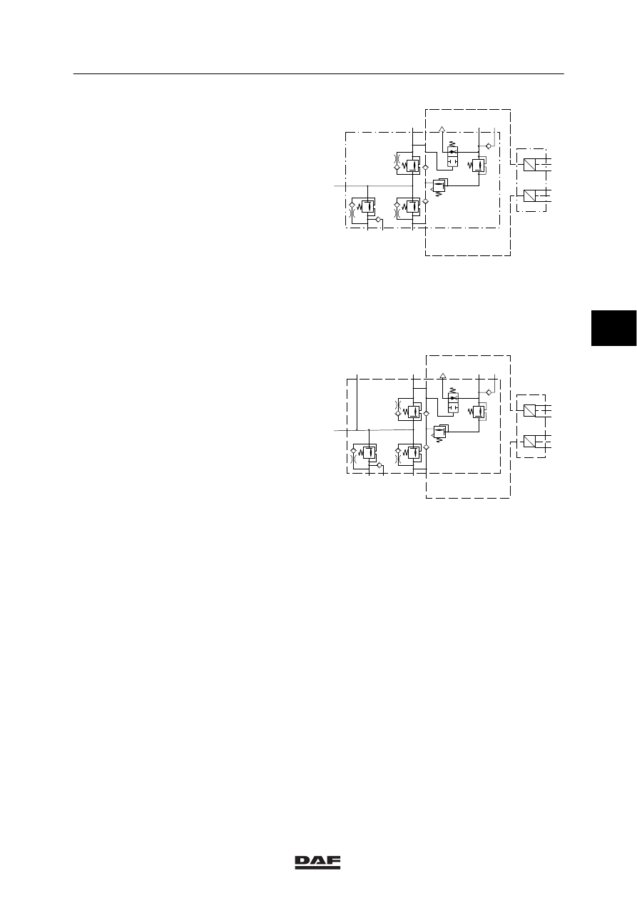
Operation, four-circuit safety valve
The air supply enters at connection 1
(connection 11 on models with air-sprung front
axle). From there, the air flows to the built-in
overflow valves of circuits 1, 2 and 4.

As soon as the valve of circuit 1 and/or circuit 2
opens, the air will be able to flow through to
circuit 3, the trailer vehicle brake and parking
brake circuit. For reasons of safety, a built-in
flow-back function empties circuit 3 when the
pressure in circuit 1 is too low. This is done to
enable the emergency brake function to be
activated.

24

1

H

26

22

21

3

23 25

P

U

6.2
6.3
6.4

P

U

6.5
6.6
6.7

R600476

model with leaf-sprung front axle

24 26

22

21

3

23 25

P

U

6.2
6.3
6.4

P

U

6.5
6.6
6.7

11

R600477

model with air-sprung front axle

4

ᓻ 200324

6

OPERATION OF BRAKE COMPONENTS

Description of components

CF65/75/85 series

2-8

2.4 WATER BLOW-OFF VALVE

Purpose
The purpose of the water blow-off valve is to
enable any condensate in the air reservoir or air
pipes to be drained and, if necessary, to vent
the system.

Operation
The valve is kept closed by the spring and the
reservoir pressure. By pushing the pin
sideways, the valve is lifted off the seat, allowing
condensate and compressed air to escape.
When the pin is released, the valve is closed.

Check that no other components are present
under the blow-off plug, as these could get
fouled during the blow-off process.

R600046

4

ᓻ 200324

6

CF65/75/85 series

Description of components

OPERATION OF BRAKE COMPONENTS

2-9

2.5 FOOT BRAKE VALVE

Purpose
The purpose of the foot brake valve is to allow
sensitive aeration and venting of both service
brake circuits, independently of each other.

R600379

Operation
The foot brake valve consists of an upper
section (circuit 1) and a lower section (circuit 2);
both have a connection point for the reservoir
pipe (11 and 12 respectively) and a connection
point for the brake line (21 and 22 respectively).
If the pedal is depressed, push rod 1, spring
retainer 2 and rubber graduating spring 3 will
exert force on graduating piston 4. The
graduating piston moves downwards, closes off
exhaust 5 and opens inlet 10. The supply
pressure at connection point 11 flows via
chamber A and connection 21 to the brake
cylinders of circuit 1.
At the same time, compressed air flows via bore
D into chamber B above graduating piston 7,
which is forced downwards as a result. Exhaust
9 is closed and inlet 8 opened. Via chamber C
and connection 22, the supply pressure at
connection 12 flows to the brake cylinders in
circuit 2.

21

22

12

A

B
D

C

10

9

7

8

6

5

4

3

2

1

11

R600748

Fig.2

4

ᓻ 200324

6

OPERATION OF BRAKE COMPONENTS

Description of components

CF65/75/85 series

2-10

The pressure being built up in chamber A is also
applied to the underside of graduating piston 4,
which is forced upwards against the pressure of
the rubber graduating spring (3), until a state of
balance is achieved. In this state of equilibrium,
both exhaust 5 and inlet 10 are closed. In the
same way, a state of balance is achieved in
circuit 2.
As the pedal is depressed further, the cycle
described above will be repeated, thus enabling
the brakes to be applied in stages, until the
maximum braking force has been applied. If the
pedal force is reduced, the rubber graduating
spring (3) will slacken so that graduating pistons
4 and 7 move upwards. The brake lines are
vented and the pressure in the brake cylinders
will fall correspondingly. If a leak occurs in the
lower circuit (circuit 2), the upper circuit will
operate as described above. If a leak occurs in
the upper circuit, no compressed air will flow to
chamber B above graduating piston 7. Piston 4
should now be depressed by the pedal deep
enough for the underside of piston tube 6 to
come into contact with graduating piston 7. The
adjustment is done in the same way as
described above. Graduating piston 7 is fitted
with two O-rings, to ensure a thorough and safe
separation between the two circuits. The space
between these two seals is connected to the
venting system. A leak can be heard
immediately as the blowing-off sound of the foot
brake valve during braking.

22

21

12

B

10

7

6

5

4

3

2

1

11

R600749

Fig.3

4

ᓻ 200324


Content   ..  891  892  893  894   ..