DAF CF65, CF75, CF85 Series . Manual - part 868
©
200423
1-13
Brake system and components
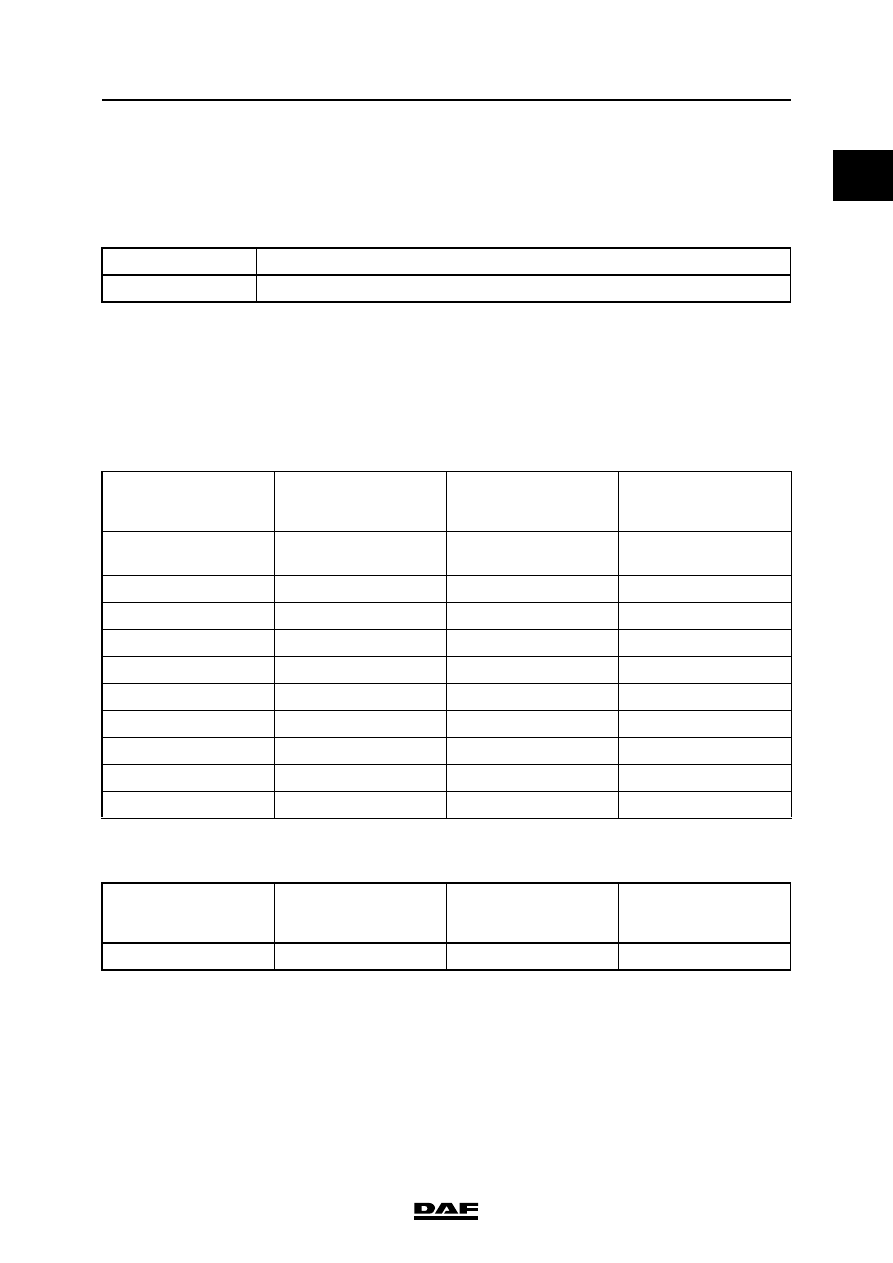
TECHNICAL DATA
ΧΦ65/75/85 series
6
0
09N044 leading rear axle (used on FTP
vehicle)
Disc brakes, SB7000 and SN7000 series
Brake drum
General
A brake drum may be used until the inside
diameter has reached the maximum permissible
value, as specified in the table below.
As soon as this diameter is exceeded, the brake
drum must be replaced.
09N044 leading rear axle (used on FTP
vehicle)
The ovality (deformation) of the brake drum is
checked with the drum in position on the hub,
or on a brake dynamometer.
Brake drums with cracks exceeding a width of
0.7 mm or a length of 50 mm may not be reused.
Minimum lining thickness
5 mm
TYPE
NOTES
DAF 1200
Fitted to all vehicles
Brake diameter
Standard brake-drum
diameter in mm
Maximum in mm
Maximum
reconditioning
dimension in mm
12
3
/
8
"
Ovality
314 +
0,127
317,3
316,3
13"
330,2 +
0,127
333,2
332,3
15
1
/
2
"
393,7
+ 0,127
396,7
395,7
16"
406,6
+ 0,250
409,6
408,6
16
1
/
2
"
420
+ 0,250
425
423
310 mm
310
+ 0,210
313
312
325 mm
325
+ 0,230
328
327
360 mm
360
+ 0,230
363
362
375 mm
375
+ 0,230
378
377
420 mm
420
+ 0,250
425
423
Brake diameter
Standard brake-drum
diameter in mm
Maximum in mm
Maximum
reconditioning
dimension in mm
300 mm
300
298 - 299 mm