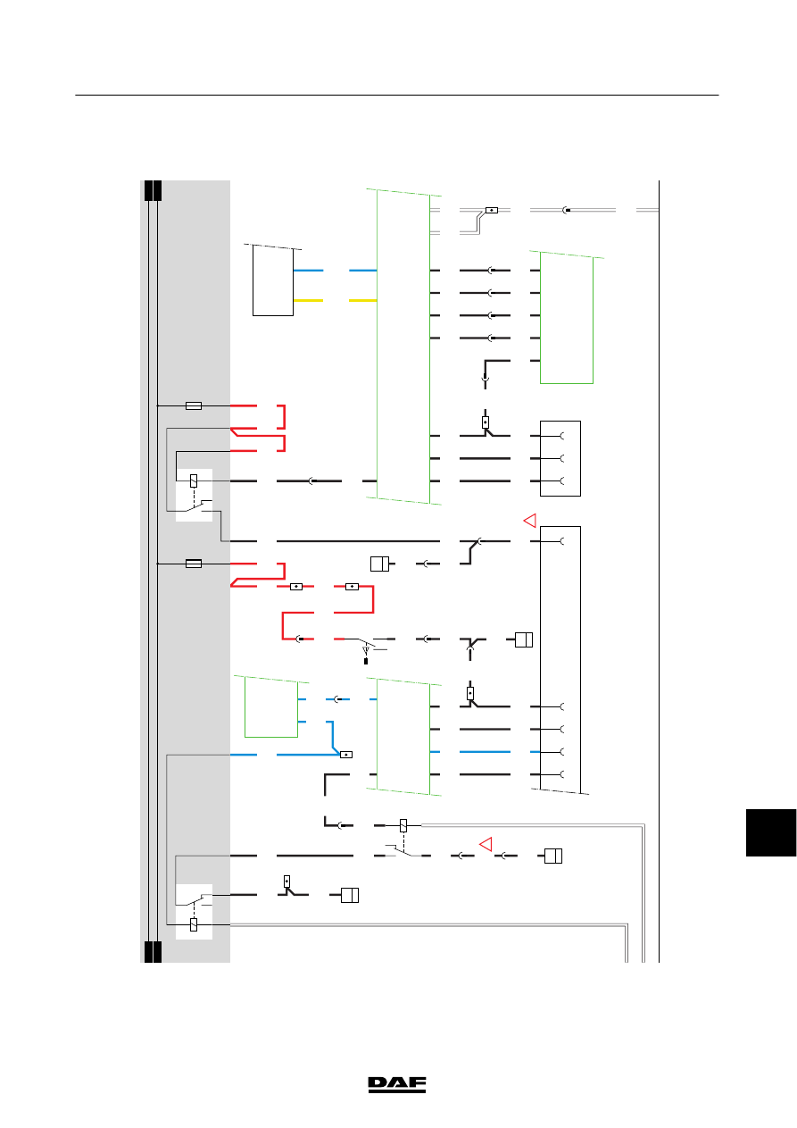
DAF CF65, CF75, CF85 Series . Manual - part 797
11
30
1358030/16-24
EL001069
107
108
1
09
110
111
112
113
114
115
116
117
118
119
120
1
21
122
123
124
125
126
127
128
129
130
131
132
133
1
34
135
136
137
138
139
1
40
141
1
42
143
144
1
45
146
147
148
149
1
50
151
152
153
1
54
155
156
157
158
159
1211
1211
1217
1217
1217
5655
4591
5655
1211
1211
1211
3458
3157
3458
4006
4051
4051
4051
4051
4591
4591
4051
5644
5644
5698
5698
5678
5678
5679
5679
5680
5680
5681
5681
9134
9134
9134
9134
5699
5699
5677
5677
5677
5677
3662
3662
5705
5705
4591
4591
3700H
3701H
4004
4004
4004
4006
4006
4186
4009
3157
4186
4009
33/403
23/403
16/401
26/403
24/403
E564
1
2
3
D866
V6
S31
S11
V28
V20
V
3
A074
4
5
17
6
18
A073
A
B
C
D814 B14
11
B176
1
12
B13/
593
C42/
594
D900
5
644
12
644
7
644
5
556
3
576
3
556
4051
2
607
3
607
4
607
5
607
17
644
1
607
D866
S13
S19
S
5
S
6
S20
S
3
S7
S8
V17
V32
S29
V4
E1
E2
G535
G203
85
2
C539
2
46
6
644
16
574
14
574
15/400
14/400
16/400
G185
87
85
86
87A
30
12/400
D867
NA
BC
D
!
!
D929
1010
1000
1010
1000
E035
10A
E016
10A
3157
1217
1217
4004
G372
3
1
25
4
G350
3
54
1
2
13/401
2/403
644
10
200332
ᓻ
2-79
Changes in the electrical system from chassis number 0E570448
5
CHANGES IN THE ELECTRICAL SYSTEM
CF65/75/85 series