DAF CF65, CF75, CF85 Series . Manual - part 783
11
A
1358030/16-24
EL001052
123456789
1
0
1
1
1
2
1
3
1
4
1
5
1
6
1
7
1
8
1
9
2
0
2
1
2
2
2
3
2
4
2
5
2
6
2
7
2
8
2
9
3
0
3
1
3
2
3
3
3
4
3
5
3
6
3
7
3
8
3
9
4
0
4
1
4
2
4
3
4
4
4
5
4
6
4
7
4
8
4
9
5
0
5
1
5
2
5
3
1008
1010
4001
4001
4001
9050
1000
1008
1008
3084
1100
1100
1100
1020
1008
1000
4002
4002
1008
1008
3084
1380
1000
1000
1380
1234
1234
1380
9050
9050
9050
1380
4004
1130
4001
1380
1010
1000
1020
1234
1381
A500
G014
1
5
G377
1
36
D911
A3
46
G203
87
2
30
87
86
85
G015
50
B010
M
31
30
G
3
B
B+
L /2
15 /3
S /4
A513
10
575
20
575
DVB
1/416
1/417
6/403
7/403
10/403
8/403
15/402
4/403
G525
G525
E286
125A
2
1
E279
5A
12
C539
1/222
2/222
4/222
6/222
12/403
7
575
D29/
595
D900
G516
D929
1010
1000
E037
15A
1000
1010
4001
1100
1234
E350
10A
30
86
85
87A
8
7
G426
8/401
25/400
1234
E351
10A
200332
ᓻ
2-23
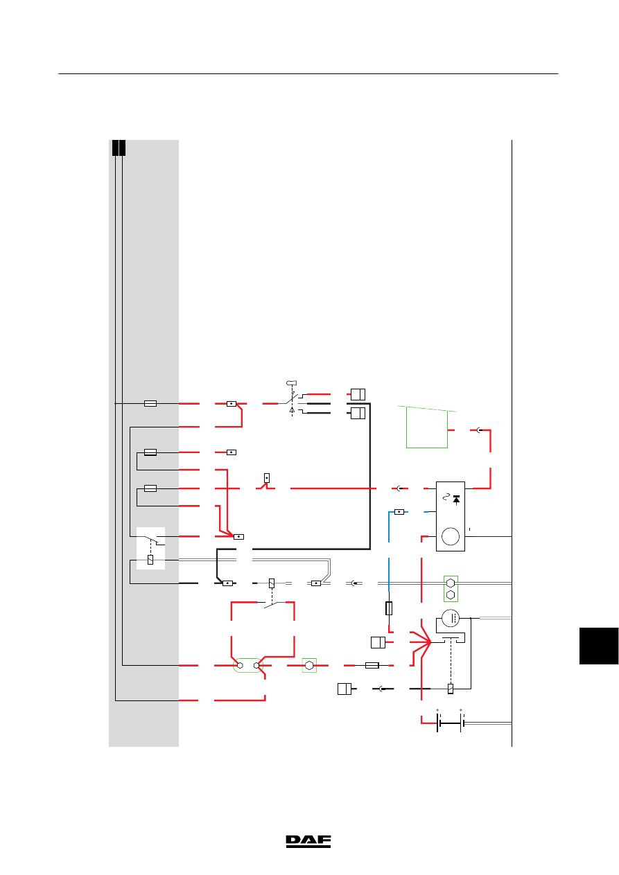
Changes in the electrical system from chassis number 0E570448
5
CHANGES IN THE ELECTRICAL SYSTEM
CF65/75/85 series