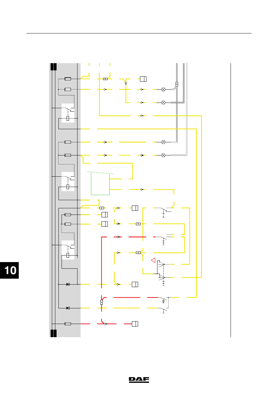
DAF CF65, CF75, CF85 Series . Manual - part 745
13
1358030/15
EL000506
1
23456789
1
0
1
1
1
2
1
3
1
4
1
5
1
6
1
7
1
8
1
9
2
0
2
1
2
2
2
3
2
4
2
5
2
6
2
7
2
8
2
9
3
0
3
1
3
2
3
3
3
4
3
5
3
6
3
7
3
8
3
9
4
0
4
1
4
2
4
3
4
4
4
5
4
6
4
7
4
8
4
9
5
0
5
1
5
2
5
3
1101
2154
2140
2120
2150
2150
2150
2100
2110
2154
1101
2154
1101
1101
1101
1101
2100
2110
2110
2110
2150
2114
2122
2122
2114
2150
2114
2110
2110
2114
2114
2113
2114
2113
2140
2110
2102
2103
1101
2100
2100
1101
1101
2110
2100
2100
2100
2100
2100
2100
2120
2123
2113
2123
2122
2123
2123
2122
2122
2122
2122
2140
2140
14/403
28/401
4
559
4
572
5
572
2
579
3
559
5
558
6
284
5
284
7
558
B129
1
35
17/403
C622
0II
I
2
14
22/401
24/401
C000
1
2
C002
1
2
7/401
16/403
C832
6
C727
3
2
0
l
ll
C773
5
71
0I
35/
595
5/
594
D900
14/566
8/566
9/566
C010
1
9
G301
3
14
G301
5
14
33/400
4
579
4
558
1
558
D929
1010
1000
1010
1000
E084
10A
D610
D609
30
86
85
87A
8
7
G001
2112
2110
E004
10A
E005
10A
2110
M
M
30
86
85
87A
8
7
G000
2101
2100
E000
10A
C011
1
9
28/400
E001
10A
30
86
85
87A
8
7
G002
2121
2120
E007
10A
E006
10A
5/402
6
288
C813
6
33
C003
1
2
C001
1
2
28/402
30/402
559
5
6
558
!
0202
ᓻ
2-76
5
ELECTRICAL SYSTEM
Electrical system
series
65/75/85
CF