DAF CF65, CF75, CF85 Series . Manual - part 617
11
1
1358030/30-34
EL001501
54
55
56
57
58
59
60
61
62
63
64
65
66
67
68
69
70
71
72
73
74
75
76
77
78
79
80
81
82
83
84
85
86
87
88
89
90
91
92
93
94
95
96
97
98
99
100
101
102
103
104
105
106
1000
1008
1008
9001
9307
9307
9307
1010
1000
1000
1010
1000
A500
1/416
1/417
E286
125A
2
1
!
1
638
20
555
30
87
G015
B525
A5/
598
D929
1010
1000
1000
1010
B010
30
2
C694
B
A
200520
3-36
5
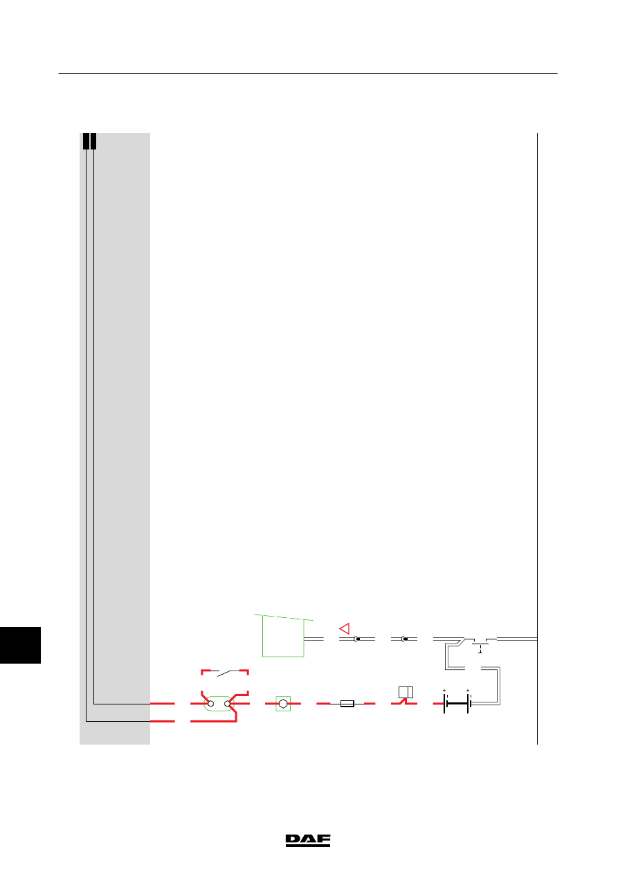
CHANGES IN THE ELECTRICAL SYSTEM
Changes in the electrical system from
chassis number 0E646818
CF65/75/85 Serie ≥0E621376