DAF CF65, CF75, CF85 Series . Manual - part 616
E502088
1000
1
2
+
+
-
-
1
2
5
85B
86
85A
88
88A
1
1
0
1
1
2
2
2
0
7
A
B
E286
G367
A500
E153
1
2
E330
4177
C854
C4
C5
A7
A2
C1
C2
A1
A3
A4
A5
2630
4179
9050
1167
M
1009
1008
4176
4178
E117
86
G015
86
G426
A1
B525
G757
C853
1167
4174
4175
3173
G367
D924
11
1M
A
IN
S
W
IT
C
H
MAIN
SWITCH
FOR
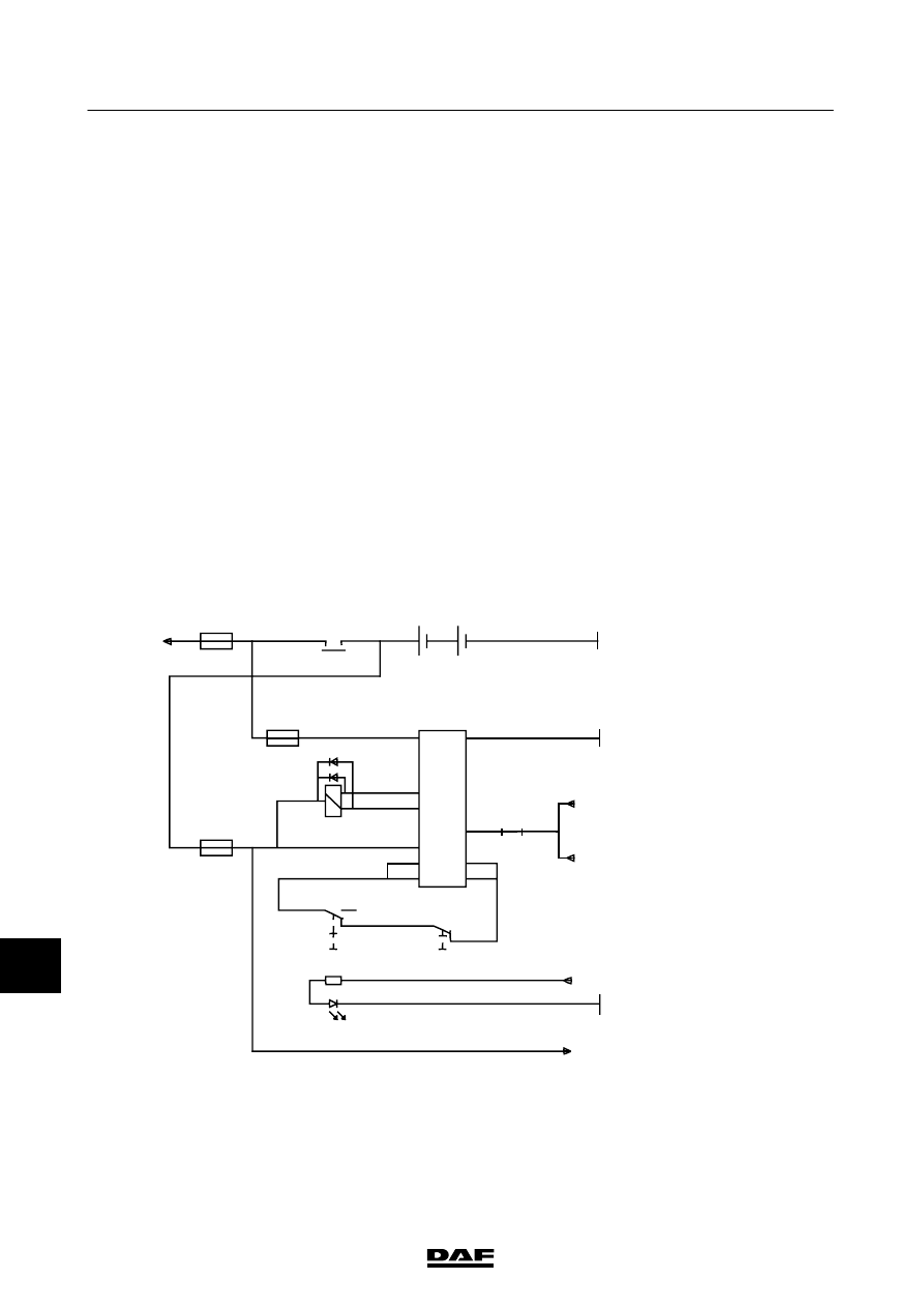
V
LG/ADR
If
the
vehicle
has
an
Allison
gearbox
and
the
syst
em
must
meet
specif
ic
saf
et
y
requirements,
wire
no.
1009
(Allison
power
supply)
should
be
connected
to
connection
88a
of
relay
G
367.
Basic
code
number
Description
A500
Batteries
B525
Modular
tachograph,
MTCO
C853
Cab
m
ain
switch
C854
Chassis
m
ain
switch
D924
Electronic
unit,
main
swit
ch
E1
17
Fuse,
search
lighting
E153
Fuse,
m
ain
switch
for
timer/engine
stop/main
switch
power
supply
E286
Main
fuse
E330
Fuse,
m
ain
switch,
“sens”
w
ire
G015
Contact
relay
G367
Relay
,main
switch
power
supply
G426
Contact
relay
G757
Through-connection between
output
A7
(wire
4179),
G
015
and
G426
via
w
ire
9050.
200520
3-32
5
CHANGES IN THE ELECTRICAL SYSTEM
Changes in the electrical system from
chassis number 0E646818
CF65/75/85 Serie ≥0E621376